Audi S5 Cabriolet (2010-2011) – fuse diagram
Year of manufacture: 2010, 2011.
Lighter fuse (socket) in Audi S5 Cabriolet (2010-2011). is the fuse 4 in the fuse box – fuse panel D (red).
Instrument panel (driver’s side)

Fuse panel A (black)
| No. | Description | Amp [A] |
| 1 | Dynamic control | 5 |
| 2 | – | – |
| 3 | Homelink | 5 |
| 4 | Line Assistant | 10 |
| 5 | Climate control | 5 |
| 6 | Right Headlight Range Adjustment | 5 |
| 7 | Left headlight range adjustment | 5 |
| 8 | Vehicle electrical control module 1 | 5 |
| 9 | Adaptive cruise control | 5 |
| 10 | Moving the gate | 5 |
| 11 | Heater wash liquid nozzles | 5 |
| 12 | Climate control | 5 |
| 13 | Mobile Phone Preparation | 5 |
| 14 | Airbag | 5 |
| 15 | Terminal 15 | 25 |
| 16 | Motor terminal 15 | 40 |
Fuse panel B (brown)
| No. | Description | Amp [A] |
| 1 | Interior rear view mirror
with automatic dimming function |
5 |
| 2 | – | – |
| 3 | Fuel Pump | 25 |
| 4 | Auxiliary water pump 3.2 l FSI | 5 |
| 5 | Left-hand seat heater with i
without seat heater |
15 |
| 30 | ||
| 6 | Electronic Stabilization Program | 10 |
| 7 | Horn | 25 |
| 8 | Left-hand door glass regulator motor | 30 |
| 9 | Windshield wiper motor | 30 |
| 10 | Electronic Stabilization Program | 25 |
| 11 | Driver’s side door control module | 15 |
| 12 | Rain and light sensor | 5 |
Fuse Panel (red)
| No. | Description | Amp [A] |
| 1 | – | – |
| 2 | – | – |
| 3 | Lumbar support | 10 |
| 4 | Dynamic control | 35 |
| 5 | – | – |
| 6 | Vehicle electrical control module 1 | 35 |
| 7 | Vehicle electrical control module 1 | 20 |
| 8 | Vehicle electrical control module 1 | 30 |
| 9 | Rear left window regulator motor | 7,5 |
| 10 | Vehicle electrical control module 1 | 30 |
| 11 | Right rear window regulator motor | 7,5 |
| 12 | Convenient Electronics | 5 |
Instrument panel (right)

Fuse holder (black)
| No. | Description | Amp [A] |
| 1 | – | – |
| 2 | – | – |
| 3 | – | – |
| 4 | – | – |
| 5 | Steering column switch module | 5 |
| 6 | Electronic Stabilization Program | 5 |
| 7 | Terminal 15 diagnostic connector | 5 |
| 8 | Gateway (Database Diagnostic Interface) | 5 |
| 9 | – | – |
| 10 | – | – |
| 11 | – | – |
| 12 | – | – |
Fuse Panel (brown)
| No. | Description | Amp [A] |
| 1 | CD / DVD drive | 5 |
| 2 | Audi drive selector module | 5 |
| 3 | MMI / Radio | 5 |
| 20 | ||
| 4 | Instrument cluster | 5 |
| 5 | Gateway
(control module for the instrument cluster) |
5 |
| 6 | Ignition lock | 5 |
| 7 | Rotary light switch | 5 |
| 8 | A/C system fan | 40 |
| 9 | Steering column lock | 5 |
| 10 | Climate control | 10 |
| 11 | Terminal 30 diagnostic connector | 10 |
| 12 | Steering column switch module | 5 |
Trunk
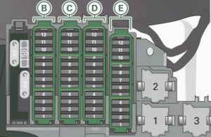
Fuse panel B (black)
| No. | Description | Amp [A] |
| 1 | Upper control unit | 10 |
| 2 | Trailer control module | 15 |
| 3 | Trailer Control Module | 20 |
| 4 | Trailer Control Module | 20 |
| 5 | Electromechanical parking brake | 5 |
| 6 | Electronic damping control | 15 |
| 7 | Electromechanical parking brake | 30 |
| 8 | Vehicle electrical control module 2 | 30 |
| 9 | Quattro Sport | 35 |
| 10 | Vehicle electrical control module 2 | 30 |
| 11 | Vehicle electrical system control module | 20 |
| 12 | Terminal 30 | 5 |
Fuse panel C (brown)
| No. | Description | Amp [A] |
| 1 | Boot lid control module;
Vehicle electrical system control module. |
30 |
| 2 | Right front seat heater | 15 |
| 3 | DCDC converter path 1 | 40 |
| 4 | DCDC converter path 2 | 40 |
| 5 | – | – |
| 6 | Right upper cabin heater | 30 |
| 7 | Electromechanical parking brake | 30 |
| 8 | Rear seat heating | 30 |
| 9 | Passenger side door configuration module | 30 |
| 10 | Left upper cabin heater | 30 |
| 11 | Passenger side door control module | 15 |
| 12 | – | – |
Fuse panel D (red)
| No. | Description | Amp [A] |
| 1 | Rear center console socket | 15 |
| 2 | Front center console exit | 15 |
| 3 | Boot Output | 15 |
| 4 | Lighter | 15 |
| 5 | V6 FSI | 5 |
| 6 | Power supply for rear seats | 5 |
| 7 | Parking system | 7,5 |
| 8 | – | – |
| 9 | Electromechanical parking brake switch | 5 |
| 10 | Audi Lateral Assistance | 5 |
| 11 | Rear seat heating | 5 |
| 12 | Terminal 15 control modules | 5 |
Fuse panel E (black)
| No. | Description | Amp [A] |
| 1 | – | – |
| 2 | – | – |
| 3 | DSP amplifier, radio | 30 |
| 20 | ||
| 4 | MMI | 7,5 |
| 5 | Radio preparation,
navigation, mobile phone. |
7,5 |
| 6 | Rear Camera | 5 |
| 7 | – | – |
| 8 | – | – |
| 9 | – | – |
| 10 | – | – |
| 11 | – | – |
| 12 | – | – |