Audi S1 (2010-2018) – fuse box diagram
Year of manufacture: 2010, 2011, 2012, 2013, 2014, 2015, 2016, 2017, 2018.
Lighter fuse (power socket) in Audi S1 (2010-2018) Is fuse 30 in fuse box C -SC-.
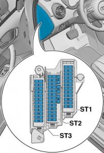
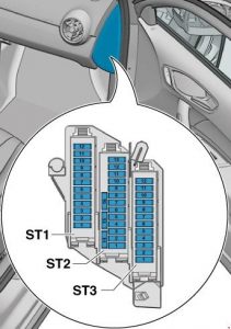
Location
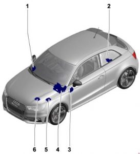
- Fuse holder D -SD-
- Fuse holder A -SA-
- Fuse holder C -SC-
- Fuse holder F -SF-
- Fuse holder B -SB-, Fuse holder H -SH-
- B -SB- Fuse Holders
Fuse holder A -SA-
On the positive terminal of the battery (only models with battery in the trunk).
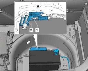
| No. | Amp [A] | Description |
| 1 | – | Empty |
| 2 | 110 | On-board power supply;
Power supply to the engine components. |
| 3 | – | Empty |
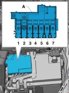
Fuse holder B -SB-
For models with battery in the engine compartment
For models with a battery in the trunk
| No. | Amp [A] | Description |
| 1 | 175 | Alternator -C- |
| 2 | 40 | Low thermal power relay -J359-;
Auxiliary air heater heating element -Z35-. |
| 3 | 110 1) | Energy on board 1)
Supply of engine components 1) |
| 4 | 80 | Power Steering Controller -J500- |
| 5 | 50 2)
40 3) |
Radiator fan thermal switch -F18-;
Radiator fan controller -J293-. |
| 6 | 50 | Automatic light period control unit -J179- |
| 7 | 60 | High thermal power relay -J360-;
Battery monitor control unit -J367 1); Additional heating element -Z35-. |
| 1) for models with battery only in the engine compartment;
2) no longer mounted, removed (model year 2011); 3) modification made (model year 2011). |
||
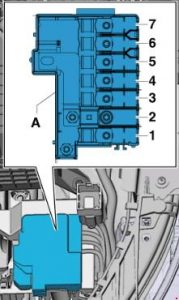
Fuses in the electronics box in fuse holder B -SB- / fuse holder H -SH-.
In the electronics box in the left engine compartment.
Only for models in the S1 version, as of January 2014
Only for models as of November 2014.
| No. | Amp [A] | Description |
| 1 | 110 4)
5 5) |
Onboard power supply 4)
Engine component supply 4) Radiator Fan Controller -J293- 5) Radiator Fan -V7-5 ) |
| 2 | 250 | Alternator -C-
Voltage regulator -C1- |
| 3 | – | Battery + |
| 4 | 80 | Power Steering Controller -J500- |
| 5 | 50 6) | Automatic light period control unit -J179-. 6)
Glow plug 1 -Q10- Glow plug 2 -Q11- Glow plug 3 -Q12- Sail 4 -Q13- |
| 6 | 50 7)
– 8) – 9) |
Heating Device -J293- Fan Control 7),
Radiator Fan -V7- 7) – |
| 7 | 125 | On-board power supply 8)
Power supply for motor components 8) |
| 4) Only for models with a battery in the engine compartment, until October 2014
5) for models from November 2014 onwards 6) only for diesel engine models, as of November 2014 7) for models up to October 2014 8) for models with battery-only engine compartment, as of November 2014 9) Fuse 5 in fuse holder B -SB5- connected |
||
Fuses in electronics box in fuse holder H -SH-.

| No. | Amp [A] | Description |
| 1 | 40 | Auxiliary air heater heating element -Z35-,
phase 1 |
| 2 | 30 | Radiator Fan Controller -J293-
Radiator Fan Controller -V7- |
| 3 | – | Empty |
| 4 | 40 | Auxiliary air heater heating element -Z35-,
phase 2 |
| 5 | 40 | Auxiliary air heater heating element -Z35-,
Grade 3 |
| 6 | 30 | Mechatronic unit for double-clutch transmission -J743- |
| 7 | 7.5 | Engine control unit -J623- |
| 8 | 20 | Wiper motor switching relay 1 -J368-
Wiper motor switching relay 2 -J369- |
| 9 | 5 | Battery Monitor Control Unit -J367- |
| 10 | 10 | Anti-interference filter -C24- |
| 11 | – | Empty |
| 12 | 10 12)
15 13) 10) 11) |
Lambda probe heater -Z19-
Lambda probe heater 1 after catalytic converter -Z29- |
| 13 | 5 | Brake light switch -F-
Clutch position transmitter -G476-. |
| 14 | 5 13)
10 10) 11) 12) |
Thermal cut-off switch for the -F163- air conditioning system.
Fuel metering valve -N290-. Oil pressure control valve -N428-. Head cooling valve -N489- Coolant circulation pump -V50- Coolant circulation pump -V55- Charge air cooling pump -V188- Auxiliary Heating Pump -V488- |
| 15 | 5 | On-board power control unit -J519-, T52c / 34
Engine control unit -J623-, T91 / 67; T94 /… Voltage stabilizer -J532-, T12aaa / 4 |
| 16 | 30 | Starter -B- |
| 17 | 15 12) 13)
30 10) 11) |
Engine control unit -J623- |
| 18 | 5 10) 11)
10 12) 13) |
Oil level and temperature sensor -G266-.
Fuel pump relay -J17- Radiator Fan Controller -J293- Low thermal power relay -J359- High Thermal Power Relay -J360- Load pressure control solenoid valve -N75-. Turbocharger recirculation valve -N249-. Intake manifold flap valve -N316-. Oil pressure control valve -N428- Oil cooling valve -N471- |
| 19 | 7, 5 10)
10 11) 13) 20 12) |
Motor element current supply relay -J757-.
Fuel pressure control valve -N276-. Fuel metering valve -N290-. Injector 2 for cylinder 1 -N532-. Injector 2 for cylinder 2 -N533-. Injector 2 for cylinder 3 -N534-. Injector 2 for cylinder 4 -N535-. Actuator 1 for camshaft adjustment -F366-. Actuator 2 for camshaft adjustment -F367- Actuator 3 for camshaft adjustment -F368- Actuator 4 for camshaft adjustment -F369- Actuator 5 for camshaft adjustment -F370- Actuator 6 for camshaft adjustment -F371-. Actuator 7 for camshaft adjustment -F372- Actuator 8 for camshaft adjustment -F373- Brake vacuum pump -V192- |
| 20 | 5 10) 11)
10 13) 20 12) |
Automatic light period control unit -J179-.
Exhaust flap control unit -J883-. Crankcase ventilation heating element -N79- Activated carbon filter solenoid valve 1 -N80- Camshaft control valve 1 -N205- Exhaust camshaft control valve 1 -N318- Continuous coolant circulation pump -V51-. Secondary air pressure sensor 1 -G609- Secondary air pressure sensor 2 -G610- |
| 10) only for models with 1.4 l diesel engine
11) only for models with 1.6 liter diesel engine 12) Only for 1.0 l / 1.4 l gasoline engine models 13) Only for 1.8 l / 2.0 l gasoline engine models |
||
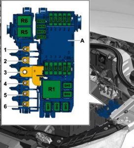
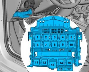
Fuse holder C -SC-
| No. | Amp [A] | Description |
| black | ||
| 1 | 30 | Digital audio pack control unit -J525-
Voltage stabilizer -J532- Radio -R- |
| 2 | 40 | Heater Controller -J65-
Relay on contact X -J59- Fresh air fan control -J126- Fresh Air Ventilator Control -V2- |
| 3 | 20 | Lighters -U1-
12 V socket -U5- |
| 4 | 15 | Trailer detector control unit -J345- |
| 5 | 5 | Data bus diagnostic interface -J533- |
| 6 | 30 | Front passenger door control unit -J387-
Right rear door control unit -J389- |
| 7 | 30 | Driver’s Door Controller -J386-
Left rear door control unit -J388- |
| 8 | 30 | Heated Rear Window Relay -J9-
Heated rear window -Z1- |
| 9 | 25 | ABS control unit -J104- |
| 10 | 20 | On-board power control unit -J519- |
| 11 | 15 | Siren high -H2-
Horn sound low -H7- Horn relay -J413- |
| 12 | 30 | On-board power control unit -J519- |
| brown | ||
| 1 | 5 | Beep tone -H12-
Anti-theft alarm sensor -G578- |
| 2 | 5 19) 16)
7,5 14) 15) 17) 18) 20) |
Terminal 30 supply voltage relay -J317-. 22)
Motronic current supply relay -J271- 21) Engine Controller -J623- |
| 3 | 5 | On-board power control unit -J519- |
| 4 | 5
15 23) |
ABS control unit -J104-
Voltage stabilizer 2 -J570- Four-wheel drive control unit -J492- 23) |
| 5 | – | Empty |
| 6 | 5 | Light sensor/combustion -G397-
Cell phone antenna amplifier -R86-. Telephone support -R126- Front roof module -WX3- |
| 7 | 15 21)
20 22) |
Fuel pump control unit -J538- 21)
Fuel pump relay -J17- 22) |
| 8 | 10 21) | Auxiliary coolant pump relay -J496-,
until October 2014 |
| 9 | 5 | Electronic steering column control unit -J527- |
| 10 | 5 | Light switch -E1- |
| 11 | 10 | Climate Controller -J255-
Climate Controller -J301- Front passenger door controller -J387- (until April 2012). Right rear door controller -J389- (until April 2012). 16-pin connector -T16-, diagnostic connection |
| 12 | 10 | Driver’s door controller -J386- (until April 2012).
Left rear door control unit -J388- (until April 2012). |
| 13 | 10 | On-board power control unit -J519-. |
| 14 | 20 | Plug-in coupler -J807-,
only for models without trailer socket |
| 15 | 30 | On-board power control unit -J519- |
| 16 | 20 | Wiper motor switching relay 1 -J368-,
by October 2014. Power supply relay for motor components -J757-. 23) 24) Ignition coil 1 with output stage -N70-. 23) 24) Ignition coil 2 with output stage -N127-. 23 ) 24) Ignition coil 3 with output stage -N291-. 23) 24) Ignition coil 4 with output stage -N292-. 23) 24) |
| Red | ||
| 1 | 5 19) 20)
20 15) 16) 17) |
Automatic light period control unit -J179-.
Vacuum pump for brakes -V192-. |
| 2 | 10
5 34) |
Brake light switch -F- (until October 2011).
Brake pedal switch -F63- (until October 2011). Auxiliary coolant pump relay -J496-. Lambda probe heater -Z19- (until October 2011). Lambda probe heater 1 after catalytic converter -Z29-, (until October 2011). Fuse 9 in fuse holder F -SF9-, (from November 2011 to October 2014) Power fuse 10 in fuse holder F -SF10-. (November 2011 to October 2014 ) ABS control unit -J104-, from November 2011 |
| 3 | 5 18) 19) 20)
7,5 16 ) 15 14 ) 15) 17) |
Air mass meter -G70-, up to October 2014.
Fuel pump relay -J17-, until October 2014. Low thermal power relay -J359-, until October 2014. High thermal power relay -J360-, until October 2014. Power supply to relay motor components -J757-, through October 2014. Fuel pressure control valve -N276-, until October 2014. Coolant circulation pump -V50-, until October 2014. |
| 4 | 15 14 ) 15) 17) 16)
25 18) 30 19 ) 20) |
Motor Controller -J623-
Clutch position transmitter -G476-, until October 2011. Brake light switch -F-, until October 2011. |
| 5 | 20 18 )
15 19) 20) 20 14) 15 ) 1 7) 30 16) |
Ignition coil 1 with output stage -N70-, until October 2014
Ignition coil 2 with output stage -N127-, until October 2014 Ignition transformer -N152-, until October 2014 Fuel pressure control valve -N276-, until October 2014 Fuel metering valve -N290-, until October 2014. Ignition coil 3 with output stage -N291-, until October 2014. Ignition coil 4 with output stage -N292-, until October 2014. |
| 6 | 10 20 16) |
Radiator fan controller -J293-, until October 2014.
Relay heater element -J925-, until October 2014. Charge pressure control solenoid valve -N75-, until October 2014. Activated carbon filter 1 solenoid valve -N80-, until October 2014. Exhaust camshaft control valve 1 -N205-, until October 2014. Turbocharger recirculation valve -N249-, until October 2014. Intake manifold flap valve -N316-, until October 2014. Exhaust camshaft control valve 1 -N318-, until October 2014. Exhaust gas recirculation switch valve -N345-, until October 2014. Oil pressure control valve -N428-, until October 2014. Intake cam regulator for cylinder 2 -N583-, until October 2014. Exhaust cam adjuster for cylinder 2 -N587-, until October 2014. Intake cam adjuster for cylinder 3 -N591-, until October 2014. Exhaust cam adjuster for cylinder 3 -N595-, until October 2014 Pump for exhaust gas recirculation cooler -V400-. |
| 7 | 5 | CD Switch -R41- |
| 8 | 5 | Internet Access Control Unit -J666-
Smart card reader control unit -J676- Radio -R- TV Tuner -R78- |
| 9 | 5 | Dashboard control unit -J285- |
| 10 | 5 | Relay for automatic anti-glare interior mirror -J910-
Auto-dimming interior mirror -Y7- |
| 11 | 7, 5 32)
15 33) |
Radio -R-
Control unit for information electronics 1 -J794-. |
| 12 | 5 | Front information display unit and operating unit control unit -J685-. |
| 14) only for models with 1.2 l gasoline engine
15) For models with 1.4 liter (90 kW) gasoline engine only (16) for models with a 1.4 liter (103 kW) gasoline engine only (17) for models with a 1.4 liter (136 kW) gasoline engine) only 18 ) only for models with a 2.0-liter (136 kW) gasoline engine 19) for models with a 1.6 liter diesel engine only (20) for models with a 2.0 liter diesel engine only for gasoline engine models only for diesel models 23) For models with a 2.0 l gasoline engine, as of January 2014. 24) For models with a 1.8 l gasoline engine, as of November 2014. 32) only for models with MMI 33) only for models without MMI 34) as of November 2011. |
||
Fuse holder D -SD-
| No. | Amp [A] | Description |
| black | ||
| 1 | 7.5 | ESL control unit -J764- |
| 2 | 20 | Trailer detector control unit -J345- |
| 3 | 20 | Trailer detector control unit -J345- |
| 4 | 30 7.5 |
Mechatronic unit for dual clutch transmission -J743-, until October 2014
Electronically controlled damping control unit -J250-, from January 2014 |
| 5 | 30 | Headlight Washer Relay System -J39-
Headlamp wash system pump -V11- |
| 6 | 5 | Interface control unit for vehicle location system -J843- |
| 7 | 7.5 | Start and input control unit -J518- |
| 8 | 15 | Mechatronic unit for double-clutch transmission -J743-, until October 2014 |
| 9 | 20 | Opening roof retractor motor -V1- |
| 10 | 7.5 | Control unit for control lever sensors -J587- |
| 11 | 15 35) | Current supply relay for motor components -J757-, through October 2014.
Fuel pressure control valve -N276-, until October 2014. |
| 12 | – | Empty |
| brown | ||
| 1 | 5 | Reversing light switch -F4-
Shift lever sensor control -J587- Mechatronic module for dual-clutch transmission -J743- |
| 2 | 10 | High pressure sensor -G65-
Oil level and temperature sensor -G266- Air conditioning system controller -J301- Power take-off relay -J807- Automatic anti-glare interior mirror -Y7- 16-pin connector -T16-, diagnostic connector |
| 3 | 5 | Data bus diagnostic interface -J533- |
| 4 | 5 | Heater control unit -J65-
Material sound control unit -J869- |
| 5 | 7.5 | Light switch -E1-
Start Relay 1 -J906- Voltage Stabilizer -J532- Start Relay 2 -J907- Relay for automatic anti-glare interior mirror -J910- Front left reflector -MX1- Front right reflector -MX2- |
| 6 | 5 | Light switch -E1- |
| 7 | 5 | ABS control unit -J104-, until October 2014.
Voltage stabilizer 2 -J570-, until October 2014. Electronically controlled damping control unit -J250-, from January 2014. |
| 8 | 5 | Heated driver’s seat adjuster -E94-
Heated front passenger seat adjuster -E95- Hazard warning light button -E229- Heated rear window button -E230- TCS and ESP button -E256- Parking aid button -E266- Tire pressure indication button -E492- Start/Stop button for operations -E693- Trailer detector control unit -J345- Left Washing Machine Heating Element -Z20- Right Washing Machine Heating Element -Z21- |
| 9 | 5 | Power Steering Controller -J500- |
| 10 | 5 36)
7,5 37) |
Air mass meter -G70-
Fuel pump controller -J538- Crankcase breather heating element -N79- |
| 11 | 5 | Airbag control unit -J234-
Passenger airbag deactivation warning light -K145-. |
| 12 | 5 | Parking aid control unit -J446- |
| 13 | 5 | Control unit for headlight range control -J431- |
| 14 | 30 | Seat heating controller -J882- |
| 15 | 15 | Rear wiper motor -V12- |
| 16 | 5 | Engine control unit -J623-
Air mass meter -G70- |
| Red | ||
| 1 | – | Emptiness |
| 2 | – | Emptiness |
| 3 | 10 | Four-wheel drive control unit -J492-,
phase-out |
| 4 | – | Emptiness |
| 5 | – | Emptiness |
| 6 | – | Emptiness |
| 7 | – | Emptiness |
| 8 | – | Emptiness |
| 9 | – | Empty |
| 10 | 5 10 |
Special vehicle control unit -J608-. |
| 11 | – | Empty |
| 12 | – | Empty |
| 35) only for models with 2.0 l gasoline engine 36) for models with gasoline engine only 37) for diesel models only |
||
Fuse holder F -SF-
| No. | Amp [A] | Description |
| 1 | 40 | Voltage Stabilizer -J532- |
| 2 | 50 | Power fuse 1 -ST1-
in fuse holder D -SD- |
| 3 | 40 | Terminal 15 supply voltage relay -J329- |
| 4 | 40 | ABS control unit -J104- |
| 5 | 5 | Voltage Stabilizer 2 -J570-, stepped |
| 6 | 5 | On-board power control unit -J519-
Voltage stabilizer -J532- Voltage Stabilizer 2 -J570-, staggered white Motor control unit -J623-. |
| 16 | 10 | Brake Light Switch -F-
(November 2011 to October 2014) Clutch position transmitter -G476-. (November 2011 to November 2014) |
| 17 | 5 | Lambda probe heater -Z19-
(November 2011 to October 2014) Heater with lambda probe 1 after catalytic converter -Z29-. (from November 2011 to November 2014) |