Audi Q7 (2005-2015) – Fuse box diagram
Year of manufacture: 2005, 2006, 2007, 2008, 2009, 2010, 2011, 2012, 2013, 2014, 2015.
Lighter fuse (power socket) in Audi Q7 (2005-2015) Is fuse 8 in the fuse box in the instrument panel (left side).
Location

- On the right, on the instrument panel
- Models with a steering wheel on the left: in the middle of the instrument panel / Models with steering wheel after right side: in the driver’s leg room
- On the right in the trunk
- Under the driver’s seat
- On the left side of the dashboard
- On the left in the plenum chamber.
- At the left rear of the engine compartment
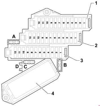
Fuse assignment in the fuse box, instrument panel on the left
| Number |
Amps [A] | Description |
| A | – | Not used |
| B | 10 | As of June 2009:
Main fuse for optional equipment -S245-. |
| C | – | Not used |
| D | – | Not used |
| Fuse holder 1 | ||
| 1 | 5 |
Until June 2010:
Unused;
As of June 2010:
Voltage Stabilizer -J532-.
|
| 2 | 5 | Until June 2010:
Unused; As of June 2010:
Relay for automatic anti-glare interior mirror -J910-.
|
| 3 | 7,5 | Until June 2010:
Unused; As of June 2010:
Electronic information control unit 1 -J794-.
|
| 4 | 5 | Until May 2010 ..:
Tire pressure monitor control unit -J502-; |
| 5 | 20 | Auxiliary heater control unit -J364- |
| 6 | 10 | LHD:
Driver’s lumbar support adjustment switch -E176-. |
| 6 | 10 | RHD:
Front passenger seat lumbar support adjustment switch -E177-. |
| 7 | 35 | LHD:
Driver’s door controller -J386- Driver’s side window regulator motor -V147- Left rear door controller -J388- Left rear window control motor -V26- |
| 7 | 35 | RHD:
Front passenger door controller -J387-. Right rear window regulator motor -V27-. Passenger windshield regulating motor -V148- |
| 8 | 15 | LHD:
Driver’s door controller -J386-; Left rear door controller -J388-. (until May 2008). |
| 8 | 15 | RHD:
Front passenger door controller -J387-. Right rear door control unit -J389-. |
| 9 | 5 |
Until May 2008 ..:
Power management control unit -J644-.
As of June 2010:
Tire pressure monitor control unit -J502-.
|
| 10 | 30 | LHD:
Input and startup control unit -J518-. Entry and start authorization switch -E415-. |
| 10 | 5 | RHD:
Media player at position 1 -R118- (until June 2009). Media player at position 2 -R119-. (until June 2009) CD Switch -R41-
(until May 2010)
DVD Player -R7-
(until May 2010)
MiniDisc player -R153-. (until June 2009) Video recorder and DVD player -R129-. (until June 2009) Connection of external sound sources -R199-. (until June 2009) |
| 11 | 10 | LHD:
Electronic steering column control unit -J527-. |
| 11 | 10 | RHD:
Climatronic rear operation and display unit -E265-. Rear fresh air fan control unit -J391- |
| 12 | 5 | LHD:
Indoor monitoring sensor -G273- Beeper -H12- |
| 12 | 5 | RHD:
comfort system central control unit -J393-. |
| Fuse holder 2 | ||
| 1 | – | Not used |
| 2 | – | Not used |
| 3 | 15 |
Until June 2009:
unused;
As of June 2009:
Left front seat ventilation control unit -J800-.
|
| 4 | 30 | Wiper motor controller -J400-;
Wiper motor -V-. |
| 5 | 5 | Light / Rain Sensor -G397- |
| 6 | 25 | Two-tone relay -J4-;
Tweeter horn -H2-; Low tone horn -H7-. |
| 7 | 30 | LHD:
On-board power control unit -J519-. |
| 7 | 25 | RHD; as of June 2010:
12 V socket 3 -U19-; 12 V socket 4 -U20-. |
| 8 | 25 | LHD:
On-board power control unit -J519-. |
| 8 | 20 | RHD:
Cigarette Lighter -U1-. |
| 9 | 25 | LHD:
On-board power control unit -J519-. |
| 9 | 25 | RHD:
12 V socket -U5-; 12 V socket 2 -U18-. |
| 10 | 10 | LHD:
In-dash control unit -J285-. (until May 2010); -J533-data bus diagnostic interface; Instrument panel -Y24-. (until May 2010). |
| 10 | 10 | RHD:
Climate controller -J255-; Fresh air fan controller -J126-. |
| 11 | 30 | Headlight washer relay system -J39- |
| 12 | 10 | 16-pin connector -T16-;
Diagnostic connector |
| Fuse holder 3 | ||
| 1 | 10 | Left Headlight |
| 2 | 5 | Control unit for adaptive cruise control -J428- Sensor heater for adaptive cruise control -Z47- |
| 3 | 5 | Direct view -J145-
Display unit button -E506- Relay valve -J541- coolant cut-off 2) Cooling heater shut-off valve -N279-. 2) |
| 4 | 10 | Lane Departure Warning
Alert control unit Track departure -J759-; Windshield heating for Lane Departure Warning -Z67-; |
| 5 | 10 5 1) |
LHD:
Signal system control unit -J616-; Control unit for special signals -E507-; As of November 2007: Multimedia Readiness (9WM). |
| 5 | 5 | RHD; as of November 2007:
Multimedia Readiness (9WM) |
| 6 | 5 | LHD:
Electronic steering column control unit -J527-; Entry and start authorization control unit -J518-; Light switch -E1-; Comfort system central control unit -J393-; Trailer detector control unit -J345-; Control unit tire pressure monitor -J502- (7K6) (as of June 2008). |
| 6 | 5 | RHD:
Heated left rear seat -Z10-; |
| 7 | 5 | Oil level and temperature transmitter -G266- |
| 8 | 5 | 16-pin connector -T16-;
Diagnostic connector. |
| 9 | 5 | Anti-glare automatic interior mirror -Y7- |
| 10 | 5 | Garage door control unit -J530-;
Garage door control unit -E284-; |
| 11 | 5 | Data bus diagnostic interface -J533- |
| 12 | 5 | Right headlight range adjuster -E102-;
Left headlight range control motor -V48-; Right headlight range control motor -V49-. |
| 12 | 5 | Air quality sensor -G238-;
Rear operation and display unit; Climatronic -E265-; Climatronic control unit -J255-. |
|
1) From November 2007
2) Only for models with generation 2 6-cylinder diesel engine |
||
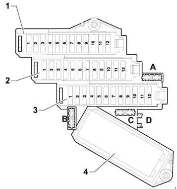
Fuse assignment in fuse box, right side instrument panel
| Number |
Amps [A] | Description |
| A | 5 | Fuse for material sound control unit -S348- |
| B | 5 | As of June 2008 ..:
Radiator fuse -S340- |
| C | – | Not used |
| D | – | Not used |
| Fuse holder 1 | ||
| 1 | 20 | Rear left heated bench seat -Z10- Rear left heated seat backrest -Z11- Heated cushion for right rear seat -Z12- Heated backrest for right rear seat -Z13- |
| 2 | 10 | Until May 2010 ..:
Automatic control unit Gearbox -J217- (0AT) |
| 2 | 5 | Until May 2010 ..:
Automatic Transmission Controller -J217-. Antenna amplifier for cell phones -R86-. |
| 3 | 30 | Heated left front seat cushion -Z45- Heated right front seat cushion -Z46- |
| 3 | 15 | RHD; since June 2009:
Right front seat ventilation control unit -J799-. |
| 4 | 20 | ABS control unit -J104- |
| 5 | 15 | LHD:
Front passenger door control unit -J387-. Right rear door control unit -J389-. (until May 2008) |
| 5 | 15 | RHD:
Driver’s Door Controller -J386- Left Rear Door Controller -J388- |
| 6 | 25 | LHD:
12 V socket 3 -U19-. |
| 6 | 25 | RHD; until May 2010 :
12 V socket 3 -U19- |
| 6 | 30 | RHD; as of June 2010:
On-board delivery control unit -J519-. |
| 7 | 10 |
LHD:
Stand adjustment switch
front passenger seat lumbar -E177-
RHD:
Driver lumbar support adjustment switch -E176-.
|
| 8 | 20 | LHD:
cigarette lighter -U1- |
| 8 | 25 | RHD:
on-board power control unit -J519-. |
| 9 | 25 | LHD:
12 V socket -U5-; 12 V socket 2 -U18- |
| 9 | 25 | RHD:
On-board power control unit -J519-. |
| 10 | 10 | LHD:
Climate controller -J255-; Fresh air fan controller -J126-. |
| 10 | 10 |
RHD:
Until June 2010:
In-dash control unit -J285-.
As of June 2010: Diagnostic interface for data bus -J533-. |
| 11 | 5 | Until May 2008 ..:
Brake light switch -F-; Brake Pedal Switch -F47-; ABS control unit -J104-.
|
| 11 | 15 | As of June 2010:
Refrigerator -J698-. |
| 12 | 15 | On-board power control unit 2 -J520- |
| Fuse holder 2 | ||
| 1 | 10 | Headlight right |
| 2 | 5 | Adaptive Suspension Control Unit -J197- |
| 3 | 5 | Mobile Phone Preparation (9ZD) |
| 4 | 5 | Propeller control unit
lane change -J769- Assistive Control Unit lane change 2 -J770- |
| 5 | 5 | Brake light damping relay -J508- Clutch pedal switch -F36- |
| 6 | 5 | Automatic control unit
Gearbox -J217- |
| 6 | 20 | Automatic control unit
Gearbox -J217- (09D) |
| 7 | 5 | ABS control unit -J104- |
| 8 | 5 | Multifunction Switch -F125- Switch Tiptronic -F189- Control unit for control lever sensors -J587- |
| 9 | 5 |
Control unit for parking aid -J446-
Control unit for overhead camera -J928-
(LHD; as of June 2012)
|
| 10 | 5 |
LHD:
Airbag control unit -J234-.
RHD:
-J533-data bus diagnostic interface.
|
| 11 | 5 | LHD:
Heated rear switch Left seat with adjuster -E128- Heated right rear switch seats with regulator -E129- |
| 11 | 5 | RHD:
Electronic Control Unit steering columns -J527-; Authorization control unit entry and commissioning -J518-; Light switch -E1-; Comfort system central control unit -J393-; Trailer detector control unit -J345-. |
| 12 | 5 | LHD:
Air quality sensor -G238-; Climatronic rear operation and display unit -E265-; Climate control unit -J255-. |
| 12 | 5 | RHD:
Right headlight range adjuster -E102-; Left headlight range control motor -V48-; Right headlight range control motor -V49-. |
| Fuse holder 3 | ||
| 1 | 15 | Until May 2007 ..:
Rear wiper motor -V12-. As of June 2008 ..: Cool Box -J698- |
| 1 | 10 | As of June 2010:
In-dash control unit -J285-. |
| 2 | 5 | Until June 2010:
Left wash nozzle heating element -Z20-; Right washer jet heating element -Z21-;
As of June 2010 ..:
Reversing camera system control unit -J772-.
|
| 3 | 30 | Until May 2010 ..:
On-board power control unit -J519-. |
| 3 | 5 | As of June 2010:
DVD Player -R7-; CD changer -R41-. |
| 4 | 5 | As of June 2009:
Visualization of front-end information and operating unit control unit -J685-. |
| 5 | 5 |
Until June 2009:
Telephone transmitter and receiver -R36-;
Until May 2010 ..:
Telephone cable -R126-;
Smart card reader control unit -J676.
|
| 5 |
10
15
|
As of June 2010:
Automatic transmission control unit -J217-. |
| 6 | 15 | Until June 2009 ..:
Front display control unit Information and control unit -J523-; Antenna amplifier -R24-. |
| 6 | 7.5 |
Until June 2009 ..:
Front display control unit
Information and operation units -J523-;
Until May 2010 ..:
Electronic information control unit 1 -J794-.
|
| 6 | 30 | As of June 2010:
Hydraulic gearbox pump relay -J510-. (only for models with start/stop system) Additional hydraulic pump control unit -J922-. (only for models with start/stop system) |
| 7 | 20 | Sliding control unit
roof adjustment -J245- |
| 8 | 20 | Rear sliding roof control -J392- |
| 9 | 20 | Roof Blind Control -J394- |
| 10 | 5 | LHD:
Media player in position 1 -R118-. (until May 2009) (until May 2009) (until May 2010) (until May 2010) (until May 2009) (until May 2009) (from November 2006 to May 2009) |
| 10 | 30 | RHD:
Input and commissioning control unit -J518-; Entry and startup authorization switch -E415-. |
| 11 | 35 | LHD:
Passenger side window regulator motor -V148-. Right rear window regulating motor -V27-. |
| 11 | 35 | RHD:
Driver’s door controller-J386-; Driver’s side window regulator motor -V147-; Left rear door controller -J388-; Left rear window control motor -V26-. |
| 12 | 10 | LHD:
Climatronic rear operation and display unit -E265-; Rear control unit fresh air blower -J391-. |
| 12 | 10 | RHD:
Electronic steering column control unit -J527-. |
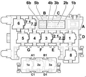
Central relay and fuse holder control panel
| Number |
Amps [A] | Description |
| A | – | Not used |
| B | 30 | Trailer detector control unit -J345-
(USA only); Brake booster (USA only). |
| C | 30 | Control unit for seat adjustment and
steering column adjustment with memory function -J136-; Control unit for adjusting the passenger seat front with memory function -J521-. |
| D | – | Not used |
| E | – | Not used |
| F | – | Not used |
| 1b | 40 | Fresh Air Fan -V2- |
| 2b | 40 | ABS control unit -J104- |
| 3b | 40 | Rear fresh air blower -V80- |
| 4b | 40 | Heated rear window -Z1- |
| 5b | 15 | As of June 2007:
Rear wiper motor -V12-. |
| 6b | 5 | As of June 2007:
Left Heating Element Washing nozzle -Z20-; Right heating element Washer nozzle -Z21-. |
| A1 | – | Not used |
| B1 | – | Not used |
| C1 | – | Not used |
| D1 | – | Not used |
| Relay | ||
| 1 | Adaptive Suspension Compressor Relay -J403- | |
| 2.1 | Terminal 75x supply voltage relay -J694-. | |
| 2.2 | Two-tone relay -J4- | |
| 3 | Headlight Washer Relay System -J39- | |
| 4 | Brake light damping relay -J508- | |
| 5 | Not used | |
| 6 | Heated Rear Window Relay -J9- | |
| 7.1 | V6 TDI / FSI, V8 MPI / FSI, V12 TDI:
Continuous coolant circulation relay -J151-. (V6 FSI June 2009) |
|
| 7.1 | As of June 2010:
Coolant shut-off valve relay -J541-. (only for models with 6 cylinders diesel engine, generation 2) |
|
| 7.2 | As of June 2010:
Automatic Anti-Glare Relay interior mirror -J910-; (only models with 8-speed automatic transmission). |
|
| 8 | Hydraulic transmission pump relay -J510- | |
| 1a | Not used | |
| 2a | Not used | |
| 3a | Not used | |
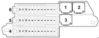
Fuse assignment in the right side fuse box in the trunk
| Number |
Amps [A] | Description |
| Fuse Holder 6 | ||
| 1 | 15 |
Until May 2010 ..:
Signal system control unit -J616-;
As of June 2010:
Multimedia system control unit -J650-.
|
| 2 | 30 | Control unit for the system
Dosage of reducing agent -J880-. |
| 3 | 15 | Until May 2010 ..:
Adaptive suspension control unit -J197-. |
| 3 | 5 | As of June 2012:
Reducing agent tank cap switch -F502-. |
| 4 | 5 | Until May 2010 ..:
Control unit for camera reversing system -J772-. Reversing camera -R189- |
| 5 | 5 | Control unit for parking aid -J446- |
| 6 | 15 | Central control unit for comfort system 2 -J773- |
| 7 | 15 | Central control unit for comfort system 2 -J773- |
| 8 | 5 | Remote Control Receiver
for auxiliary heater -R64- |
| 9 | 20 | 12 V socket 5 -U26- |
| 10 | 20 | Central control unit of the comfort system -J393- |
| 11 | 15 | Antenna reader for the system
keyless opening system for vehicles -J723- |
| 12 | 30 | Central control unit of the comfort system -J393- |
| Fuse holder 5 | ||
| 1 | 15 | Signal System Control Unit -J616- |
| 2 | 5 | Special Signal Processing Unit -E507- |
| 3 | 15 | Two-way radio relay -J84- Two-Way Radio Relay -R8- |
| 4 | 15 | Two-way radio relay -J84- Two-Way Radio Relay -R8- |
| 5 | 5 | Radio -R- |
| 5 | 15 | As of June 2010:
Signal system control unit -J616-. |
| 6 | 5 | Until June 2009 ..:
TV Tuner -R78-. |
| 7 | 5 | Until June 2009:
Navigation system with CD drive control unit -J401-. |
| 8 | 30 | Until June 2009 ..:
Digital audio pack control unit -J525-. |
| 9 | 5 | Until June 2009 ..:
Digital Radio -R147- |
| 10 | 30 | Until June 2009 ..:
Digital audio package control unit 2 -J787-. |
| 11 | 5 | Until June 2009 ..:
Control unit for camera reversing system -J772-. Until June 2009 ..: Reversing Camera -R189- |
| 12 | – | Not used |
| Fuse holder 4 | ||
| 1 | 5 | June 2009 to May 2010:
Radio -R- |
| 1 |
7,5
30
|
As of June 2010:
Digital audio pack control unit -J525-. |
| 2 | 5 | As of June 2009:
TV Tuner -R78-. As of June 2011: Digital TV Tuner -R171-. |
| 3 | 30 | As of June 2009:
Digital audio pack control unit -J525-. |
| 4 | 30 | As of June 2009:
Digital Control Unit Sound Package 2 -J787- |
| 5 | 15 | Rear seat entertainment (9WP, 9WK)
(November 2007 to May 2010) Multimedia System Control Unit -J650-
(until May 2010)
Adaptive suspension control unit -J197-.
(as of June 2010)
|
| 6 | 20 | Central control unit of the comfort system -J393- |
| 7 | 30 | Rear cover controller -J605- ;
Motor on rear cover controller -V375-. |
| 8 | 30 | Back Cover Controller 2 -J756-;
Motor on rear cover controller 2 -V376-. |
| 9 | 15 | Trailer detector control unit -J345- |
| 10 | 15 20 1) |
Trailer detector control unit -J345- |
| 11 | 15 20 1) |
Trailer detector control unit -J345-. |
| 12 | 30 25 1) |
Trailer detector control unit -J345- Motor with articulated ball head -V317-. |
| Relay | ||
| 1 | Not used | |
| 2 | Not used | |
| 3 | As of November 2007:
6-pin connector -T6am-, Rear entertainment |
|
| 1) As of June 2007 |
||
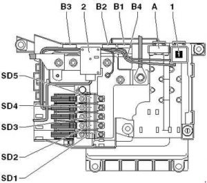
Fuse assignment in the fuse box under the driver’s seat
| Number |
Amps [A] | Description |
| 2 | – | Battery isolation switch -N253- |
| A | 40 | Self Leveling Suspension Fuse -S110- |
| B1 | 30 | As of June 2010:
Fuse 1 (30) -S204-. |
| B2 | 5 | As of June 2008:
Vehicle location system fuse -S347-. |
| B3 | – | Not used |
| B4 | 30 | As of June 2010:
Fuse 2 (30) -S205-. |
| SD1 | 150 | Fuse 1 in fuse holder D -SD1- |
| SD2 | 125 | Until May 2006 ..:
Fuse 2 in fuse holder D -SD2-. |
| SD2 | 150 | As of June 2006:
Fuse 2 in fuse holder D -SD2-. |
| SD3 | 50 | Fuse 3 in fuse holder D -SD3- |
| SD4 | 60 | Fuse 4 in fuse holder D -SD4- |
| SD5 | 125 | Fuse 5 in fuse holder D -SD5- |
| Relay | ||
| 1 | Terminal 15 supply voltage relay -J329- | |
Relay and fuse holder in the engine compartment electronics box (gasoline engine)
| Number |
Amps [A] | Description |
| 1 |
40
60
|
Radiator Fan -V7- |
| 2 | 50 | Secondary air pump motor -V101- |
| 3 | – | Not used |
| 4 |
40
60
|
Radiator Fan 2 -V177- |
| 5 | 50 | Secondary air pump motor 2 -V189- |
| 6 | – | Not used |
| 7 | 30 20 4) |
Ignition Coils |
| 8 | 5 | Radiator Fan Controller -J293-;
Radiator fan controller 2 -J671-. |
| 9 | 15 | Engine control unit -J623-;
Injectors. |
| 10 | 10 | High pressure shipper -G65- 1) 2) 3);
Circulatory cooling fluid -V50-. 1); Map-controlled engine cooling system thermostat -F265-. 1); Continuous cooling circuit relay -J151-. 1) Control valve 1 -N205- 1 ) 2) 3); Camshaft control valve 2 -N208-1 ) 3) Intake manifold flap valve -N316-1 ) Exhaust camshaft control valve 1 -N318-1 ) 2) Exhaust camshaft control valve 2 -N319-1 ) Intake manifold flap valve 2 -N403- 1) Charge only air-cooling pump -V188-3 ) |
| 11 | 5 | Engine control unit -J623-;
Air mass meter -G70-2 ); |
| 12 | 5 | Crankcase breather heating element -N79- |
| 13 | 15 | Airflow Meter -G70- 1)
Airflow Meter 2 -G246- 1); Solenoid valve with activated carbon filter 1 -N80- 1) 2) ; Secondary air inlet valve -N112-. 1) 3) Fuel metering valve -N290-. 1) 2 ) intake manifold valve cover -N316-. 2) 3) Secondary valve inlet 2 -N320-. 1) 3) fuel metering valve 2 -N402-. 1) oil pressure control valve -N428- 3) cd coolant circulation pump -V51-. 3 ) Fuel system diagnostic pump -V144- 1) 2) 3) System shut-off valve only crankcase ventilation -N548-3 ) |
| 14 | 15 | Lambda Probe -G39-;
Lambda Probe 2 -G108-. |
| 15 | 15 | Lambda probe after catalytic converter -G130-;
Lambda probe 2 after catalytic converter -G131-. |
| 16 | 30 | Fuel pump control unit -J538- |
| 17 | 5 | Engine control unit -J623- |
| 18 | 15 | Brake Vacuum Pump -V192-1 ) 2) |
| Relay | ||
| A1 | Start-up Relay -J53- 5) Motor component current supply relay -J757-. 6) |
|
| A2 | Start Relay 2 -J695- 5) Motronic Power Supply Relay -J271- 6) |
|
| A3 | Motor element power supply relay -J757- 5) |
|
| A4 | Secondary air pump relay -J299- 1,3) |
|
| A5 | Brake Servo Relay -J569- 5) Starter Relay -J53- 6) |
|
| A6 | Continuous Coolant Circulation Relay -J151- 5) Start Relay 2 -J695- 6) |
|
| B1 | Not used | |
| B2 | Not used | |
| B3 | Fuel Pump Relay -J17- 5) | |
| B4 | Not used | |
| B5 | Fuel Coolant Pump Relay -J445-5 ) | |
| B6 | Not used | |
| C1 | Circulation pump relay -J160- 1) Brake booster relay -J569- 2) Auxiliary coolant pump relay -J496- 3) |
|
| C2 | Motronic Power Supply Relay -J271-5 ) | |
| 1) Only for BAR engine codes 2) Only for engine codes BHK, BHL 3) For engine codes CJTC, CJTB, CJWB,CNAA, CJWC, CTWA, CTWB, CJWE;4) From June 2010 5) Until June 2009 6) From June 2009 |
||
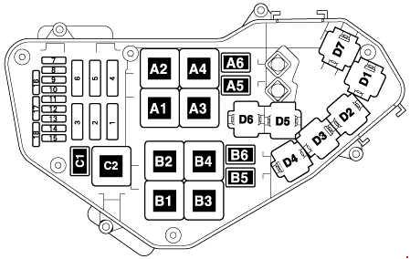
Relay and fuse holder in the engine compartment electronics box (diesel engine)

| Number |
Amps [A] | Description |
| 1 | 60 | Radiator Fan Controller -J293-
Radiator Fan Controller -V7- |
| 2 | 80 | Automatic light period control unit -J179-. |
| 3 | 40 | Auxiliary heating element
Air Heater -Z35- (400 W) 4) 11) 13) |
| 4 | 40 1)
60 2) |
Radiator Fan Controller 2 -J671-
Radiator Fan Controller 2 -V177- |
| 5 | 80 60 13) 15) |
Light period controller 2 -J703-. 3) 5) 6) 10)
Level 3 heating relay -J959-13 ) 15) |
| 6 | 80 60 13) 15) |
Auxiliary heating element
Air Heater -Z35- (2 x 400 W) 4) 11) |
| 7 | 15 | Map-controlled engine cooling system thermostat -F265-. 9) 13)
Automatic light period control unit -J179-. Thermal Low Power Relay -J359-4 ) 11) 13) High thermal power relay -J360-. 4) 11) 13) Turbocharger controller 1 -J724- 7)Turbocharger controller 2 -J725- 6) Charge air cooler bypass controller -J865-4 ) 11) Exhaust gas recirculation valve -N18 -. 7) Exhaust gas recirculation radiator switch valve 2 -N345-Exhaust gas recirculation radiator switch valve 2 -N381-. 4) 11) 9) 13) Oil pressure control valve -N428-. Electro-hydraulic engine mount solenoid valve -N398-. Cylinder head cooling valve -N489-. 9) 10) 13) Intake manifold handle motor -V157- 6) 7) Intake manifold handle motor 2 -V275- 7) only |
| 8 | 5 | Radiator Fan Controller -J293-;
Radiator fan controller 2 -J671-. |
| 9 | 15 | Motor Controller -J623-
Engine Controller 2 -J624-3 ) 5) 6) 10) |
| 10 | 10 | Fuel pressure control valve -N276-
Fuel metering valve -N290-. Fuel dosing valve 2 -N402-. 5) Fuel pressure control valve 2 -N484-. 5) only |
| 11 | 15 10 9) 11) |
Lambda Sensor -G39-
Lambda Probe 2 -G108- 3) 5) 6) 10) Lambda probe heater -Z19- Lambda Probe Heater 2 -Z28- 3) 5) 6) 10) |
| 12 | 10 5 4) 14) |
Fuel cooling pump relay -J445-. 3) 5) 6)
NOx Sensor Controller -J583-4 ) 13) NOx sensor controller 2 -J881-4 ) 11) 13) Fuel Coolant Pump -V166- 3) 6) Exhaust gas recirculation pump -V400-. 3) 5) 10) free 7) 8) 9) Particulate matter sensor only -G784-. 13) |
| 13 | 10 15 4) 5) |
High pressure sensor -G65-
Continuous refrigerant circulation relay -J151- Fuel coolant pump relay -J445-4 ) 7) 8) Light Period Controller 2 -J703-3 ) 5) 6) 10) Exhaust gas recirculation cooler switching valve 2 -N381-. 5) Coolant circulation pump -V50-. Continuous coolant circulation pump -V51- 4) 8) 10) 11) Fuel cooling pump -V166- 4) 7) 8) Intake manifold handle motor 2 -V275-. 6 ) Exhaust gas recirculation radiator pump -V400- 4) 8) |
| 14 | 5 | Air mass meter -G70-
Air mass meter 2 -G246- 3) 5) 6) 10) |
| 15 | 5 | Motor Controller -J623-
Engine Controller 2 -J624-3 ) 5) 6) 10) |
| 16 | 20 25 |
Fuel system pressure pump -G6-
Fuel pump controller -J538- 9) 10) 13) |
| 17 | 20 | Fuel Pump -G23- 5) 6) 7) 8) |
| 10 | Pressure sensor for reducing agent dosing system -G686-4 )
Reducing Agent Pump -V437-4 ) Reducing agent pump heater -Z103-4 ) only |
|
| 5 | Motor Controller -J623- 9) 10) 11) 13)
Engine Controller 2 -J624-10 ) only |
|
| 18 | 7.5 | Crankcase breather heating element -N79- 3) 5) 6) 10)
Crankcase ventilation heating element 2 -N483-3 ) 5) 10) |
| 20 | Auxiliary fuel pump relay -J832- 4) 8)
Additional fuel pump -V393- 4) 8) |
|
| 10 5 12) |
Pressure sensor for reducing agent dosing system -G686-. 11) 13)
Reducing agent pump -V437-. 11) 13) Reducing agent pump heater -Z103-. 11) 13) |
|
| Relay | ||
| A1 | Automatic light period control unit -J179-. | |
| A2 | Until June 2009; V12:
Match Relay -J53-; As of June 2009: Terminal 30 supply voltage relay -J317-. |
|
| A3 | CCGA, CCFA, CCFC, V12:
Light period control unit 2 -J703-. |
|
| A4 | Until June 2009; V12:
Start Relay 2 -J695-. Auxiliary Fuel Pump Relay -J832- |
|
| A5 | Until June 2009:
not used Departure Relay -J53-. |
|
| A6 | Until June 2009:
Auxiliary fuel pump relay -J832-. As of June 2009: Start Relay 2 -J695-. |
|
| B1 | CCMA, CATA, CLZB, CNRB:
-J359- low thermal power relay. |
|
| B2 | Not used | |
| B3 | Until June 2009:
Fuel pump relay -J17-; From June 2009; CLZB, CNRB : Relay for 3rd heating setting -J959-. |
|
| B4 | CCMA, CATA, CLZB, CNRB:
High power thermal relay -J360-. |
|
| B5 | Until June 2009; V12:
Fuel coolant pump relay -J445-; As of June 2009; CCFA : Fuel pump relay for auxiliary heater -J749-. |
|
| B6 | CCGA, V12:
Auxiliary coolant pump relay -J496-. |
|
| C1 | Until June 2009; V12:
Fuel pump relay for auxiliary heater -J749-. As of June 2009; CCMA, CATA, CCFA : Fuel Coolant Pump Relay – J445 |
|
| C2 | Until June 2009; V12:
Terminal 30 supply voltage relay -J317-. As of June 2009; CCFA : Fuel Pump Relay -J17- |
|
| 1) Models without trailer hitch 2) Models with with trailer hitch 3) For engine code CCFA 4) For engine code CCMA , CATA until May 2010 5) For engine code CCGA 6) For engine code BTR 7) For engine code BUN, BUG 8) For engine codes CASA, CASB (9) For engine codes CJGA, CJMA, CJGC, CJGD, CRCA, CNRA (10) For engine code CCFC 11) For engine codes CCMA, CATA as of June 2010 12) From June 2010 13) For engines with code CLZB, CNRB 14) Models without particle sensor 15) As of June 2012 |
||
Wiring connector 2 terminal 30 -TV22- / slave start socket -U6-.