Audi A4 B7 (8E, 8H) (2004-2008) – fuse box diagram
Year of manufacture: 2004, 2005, 2006, 2007, 2008, 2009.
Lighter fuse (socket) on Audi A4 B7 (2004-2009) Is fuse 33 in the fuse box in the passenger compartment.
Fuse box in the passenger compartment
Location of the fuse box
The Audi A4 B7 fuse box is located on the left side of the instrument panel:
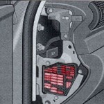
To access, open the left side door and remove the instrument panel side cover by pressing on it.
Fuse box diagram
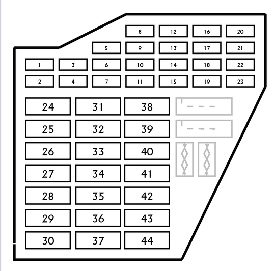
| No. | Amps [A] | Description |
|---|---|---|
| 1 | 10 A | Air conditioning controller;
Climatronic. |
| 2 | 5A | Footlights |
| 3 | 5A | Heated windscreen washer nozzles |
| 4 | 5A | Cooling Fan Control Unit |
| 5 | 10 A | Rear roller shutter;
Multifunction switch; Oil level sensor; Oil temperature sensor; Navigation system; Park Assist Controller. |
| 6 | 5A | Air quality sensor;
Climatronic; Heated front seats; High pressure air conditioning sensor; TCS/ESP button, |
| 7 | 10 A | Traction control switch;
Clutch switch; ABS controller; Brake pedal switch. |
| 8 | 5A | Phone;
Telephone Amplifier. |
| 9 | 15A | Servo Brake Relay |
| 10 | 5A | Headlight Range Control |
| 11 | 5A | Airbag control unit;
Airbag warning light. |
| 12 | 10 A | Diagnostic connector |
| 13 | 10 A | Control unit, electronic steering column |
| 14 | 10 A | Brake light switch |
| 15 | 10 A | Control unit with display on the instrument panel;
Navigation system; CD player. |
| 16 | 5A | Garage Door Opener |
| 17 | 10 A | Rain sensor;
Daytime operation system; Park assist controller. |
| 18 | 5A | |
| 19 | 15A | Fog Lights |
| 20 | Not used | |
| 21 | Not used | |
| 22 | 15A | Left front door controller;
Right front door controller. |
| 23 | 15A | Left rear door controller;
Right tailgate controller. |
| 24 | 20A | Electric Comfort System |
| 25 | 30A | Blower;
Air Conditioning. |
| 26 | 30A | Heated rear window |
| 27 | 30A | Trailer detection control unit |
| 28 | 20A | Fuel Pump |
| 29 | Not used | |
| 30 | 20A | Sliding Roof Controller |
| 31 | 15A | Reversing light switch;
Mass flow meter; Automatic transmission controller; Light sensor; Starter Relay; Selector cable closure solenoid; Diagnostic connector; Automatic anti-glare rear-view mirror. |
| 32 | Not used | |
| 33 | 15A | Lighter |
| 34 | 30A | 12V Socket |
| 35 | 30A | Accessory socket |
| 36 | 30A | Power control unit;
Rear wiper motor. |
| 37 | 30A | Power controller;
Headlight wash pump. |
| 38 | 15A | Alarm horn;
Electric comfort system; Interior control |
| 39 | 20A | Radio Sound Amplifier |
| 40 | 25A | Horn |
| 41 | Additional heater control unit;
Remote control receiver. |
|
| 42 | 30A | ABS control unit |
| 43 | 15A | Mass airflow meter;
Engine management; EGR; Main courier; Engine control unit; Engine control unit relay. |
| 44 | 30A | Climate control unit |
Fuse and relay box №1.
Diagram of the fuse box.
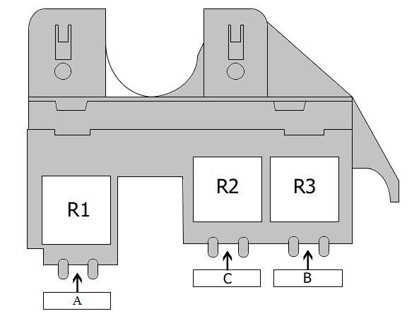
legend.
| No. | Amps [A] | Description |
|---|---|---|
| A | Not used | |
| b | 40A | Additional Heater |
| C | 60A | Additional Heater |
| R1 | Special vehicles | |
| R2 | Low power heating relay | |
| R3 | High Performance Heating Relay |
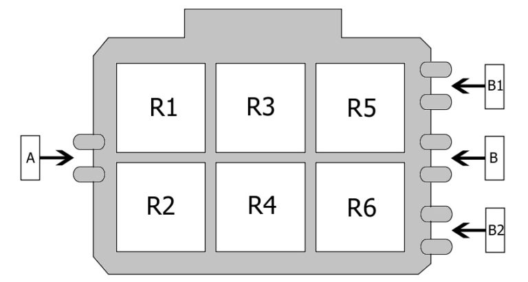
Fuse and relay box 2 in passenger compartment
Fuse box diagram
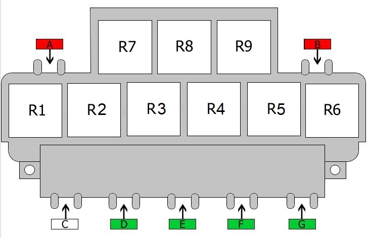
| No. | Amps [A] | Description |
|---|---|---|
| A | 10 A | Rear roller blind |
| B1 | 10 A | 12V Socket |
| B2 | 10 A | Rear roller blind |
| C | not used | |
| D | 30A | Window Regulator |
| E1 | 30A | Driver’s seat adjustment |
| E2 | 10 A | Driver’s seat adjustment |
| F | 30A | Window Regulator |
| g | 30A | Towing Module |
| R1 | Fuel pump relay;
Additional fuel pump relay. |
|
| R2 | Servo Control Unit | |
| R3 | Starter Relay | |
| R4 | Starter motor relay;
Brake servo relay. |
|
| R5 | Heated rear window relay | |
| R6 | X contact relay | |
| R7 | Not used | |
| R8 | Horn relay | |
| R9 | Not used |
Fuse and relay box 3 in passenger compartment
Fuse box diagram
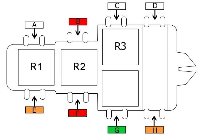
| No. | Amps [A] | Description |
|---|---|---|
| A | Not used | |
| B | 10 A | Pest Repellent System |
| C | Not used | |
| D | Not used | |
| E | 40A | Special Vehicles |
| F1 | 10 A | Special vehicles |
| F2 | 40A | Cooling Fan (also 60A) |
| G | 30A | Cooling fan (also used 40A and 60A) |
| H | 40A | ABS control unit |
| R1 | Not used | |
| R2 | Not used | |
| R3 | Special vehicles | |
| R4A | Special Vehicles | |
| R4B | Cab package |
Relay box in passenger compartment
Diagram of the relay box
| No. | Amps [A] | DESCRIPTION |
|---|---|---|
| A | Not used | |
| B | Not used | |
| B1 | Not used | |
| B2 | Not used | |
| R1 | Alarm system;
Traffic lights; High beam relay. |
|
| R2 | Special Vehicles;
Cab package. |
|
| R3 | Alarm system control unit or relay siren |
|
| R4 | Alarm system control unit or relay siren |
|
| R5 | Alarm relay;
Right Indicator |
|
| R6 | Alarm relay Left Indicator or Not used |
Fuse box 2 in passenger compartment
Fuse box diagram
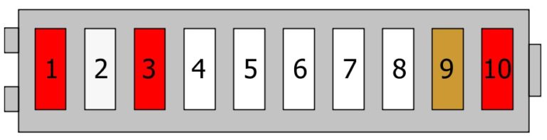
| No. | Amps [A] | Description |
|---|---|---|
| 1 | 10 A | Special vehicles or Cab package |
| 2 | 25A | Special Vehicles or alarm system |
| 3 | 10 A | Special vehicles or Cab package |
| 4 | Special vehicles | |
| 5 | Special Vehicles | |
| 6 | Special vehicles | |
| 7 | Special vehicles | |
| 8 | Special vehicles | |
| 9 | 5A | Special Vehicles or radio |
| 10 | 10 A | Special vehicles or 12V Socket |
Fuse box in engine compartment Audi A4 (B7)
Diagram of the fuse box
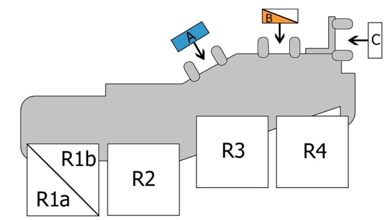
| No. | Amps [A] | Description |
|---|---|---|
| A | 15A | Motor Electronics |
| B1 | Not used | |
| B2 | 40A | Secondary Air Injection Pump |
| C | Not used | |
| D | 20A | Motor Control Unit |
| E | 15A | Injectors |
| F | Not used | |
| G | 15A | Motor Electronics |
| R1a | Not used | |
| R1b | Not used | |
| R2 | Main relay | |
| R3 | Secondary air pump relay | |
| R4 | Not used |
This is applicable for engine models:
2004, 2005, 2006, 2007 and 2008 Audi A4 B7 Petrol (1.6, 1.8T, 2.0, 3.2) and Diesel (1.9 TDI, 2.5 TDI, 2.7 TDI and 3.0 TDI), S4, RS4.