Audi A3 8P (2003-2013) – Fuse box diagram
Year of manufacture: 2003, 2004, 2005, 2006, 2007, 2008, 2009, 2010, 2011, 2012, 2013.
Lighter fuse (socket) on Audi A3 8P (2003-2013) Is fuse 24 in the fuse box in the instrument panel.
The Audi A3 8P (2003-2013) has 2 fuse locations. One is located in the driver side instrument panel and the other in the engine compartment.
Driver-side fuse box in the instrument panel
To access the fuse box located on the driver’s side of the instrument panel, open the driver’s door and remove the instrument panel fuse cover using the ignition key or a screwdriver.
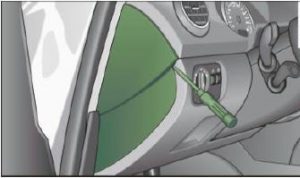
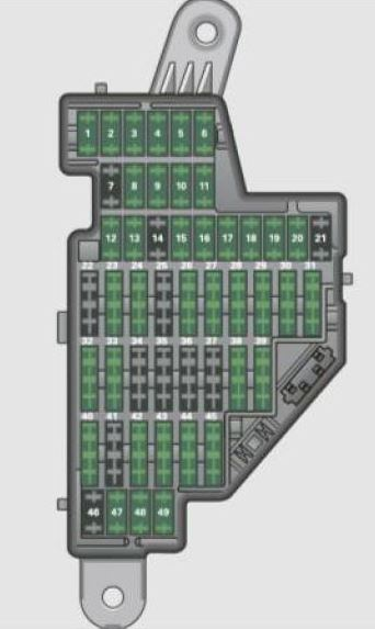
Diagram of the Audi A3 8P fuse box – driver’s side of the instrument panel
| No. | Description | Amps [A] |
| 1 | Engine components (I);
Manual headlight adjustment; Automatic headlight adjustment; AFS control module; Engine components (II); Light switch (light switch); Diagnostic socket. |
10 |
| 2 | All-Wheel Drive;
Automatic transmission; Control module for CAN data transmission (gateway); Electromechanical control; Automatic transmission with shift gate; Engine relay; Fuel tank controller; Engine controller; Brake control (ABS); Electronic stability program (ESP); Antiskid control (ASRL) Brake light switch. |
10 |
| 3 | Airbag | 5 |
| 4 | Air conditioning (pressure sensor, air quality sensor);
Electronic stability program (ESP) button; Anti-skid control (ASRI); Oil level sensor (WIV); Reversing light switch; Front seat heating; Seat occupancy recognition; Navigation; Garage door opener; Automatic dimming of the mirrors; Heated windshield washer nozzles; Air conditioning (control module). |
5 |
| 5 | AFS Headlights (left side) | 5 |
| 6 | AFS Headlights (right side) | 5 |
| 7 | – | – |
| 8 | – | – |
| 9 | – | – |
| 10 | – | – |
| 11 | – | – |
| 12 | Central locking (front doors) | 10 |
| 13 | Central locking (rear door);
Convenient electronics (control module). |
10 |
| 14 | Electronic stabilization program (ESP) (control module);
Automatic transmission (control module, Automatic transmission with shift gate) |
10 |
| 15 | Interior lighting;
Reading lamps. |
10 |
| 16 | Diagnostic connector;
Rain sensor; Air conditioning (control module). |
10 |
| 17 | Theft Warning System | 5 |
| 18 | Diag Starter | 5 |
| 19 | – | – |
| 20 | – | – |
| 21 | – | – |
| 22 | Air conditioning (blower) | 40 |
| 23 | Driver’s side windshield | 30 |
| 24 | Lighter | 20 |
| 25 | Rear window defogger | 30 |
| 26 | Power socket in the trunk | 20 |
| 27 | Fuel tank control module;
Fuel pump. |
15 |
| 28 | Electric window – rear | 30 |
| 29 | – | – |
| 30 | Automatic transmission | 20 |
| 31 | Automatic transmission (vacuum pump) | 20 |
| 32 | – | – |
| 33 | Sliding/raising roof | 20 |
| 34 | – | – |
| 35 | – | – |
| 36 | Lumbar support | 10 |
| 37 | Heated front seats | 20 |
| 38 | Passenger-side windshield | 30 |
| 39 | – | – |
| 40 | Heating (blower) | 40 |
| 41 | Rear window wiper | 15 |
| 42 | Windshield Wiper (washer pump) | 15 |
| 43 | Convenient electronics (control module) | 20 |
| 44 | Trailer Control Module | 20 |
| 45 | Trailer control module | 15 |
| 46 | – | – |
| 47 | Mobile Phone Package (VDA interface) | 5 |
| 48 | – | – |
| 49 | – | – |
2- Fuse box in the engine compartment – left side
To access the fuse box located in the engine compartment, unlock the fuse cover, push the two sliders forward.
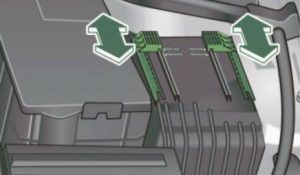
Diagram of the Audi A3 8P fuse box – Engine compartment – left side
Check the fuse arrangement in your car, there are two different arrangements. Check the fuse arrangement with the fuse panel cover removed.
Some of the equipment listed is optional or only available on certain model configurations.
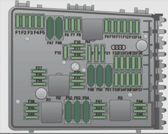
Variation (1) with 30 plug-in fuses
| No. | Description | Amps [A] |
| F1 | – | – |
| F2 | Steering wheel electronics | 5 |
| F3 | Accumulator voltage | 5 |
| F4 | Antilock brake system valves (ABS) | 30 |
| F5 | Gearbox control module | 15 |
| F6 | Instrument Grouping Module | 5 |
| F7 | Gearbox control module | 30 |
| F8 | Navigation system;
Radio system. |
15 |
| 25 | ||
| F9 | Navigation system;
Digital radio; Mobile; Television equipment. |
5 |
| F10 | Motor control module;
Main courier. |
5 |
| 10 | ||
| F11 | – | – |
| F12 | Control module for CAN data transmission (gateway) | 5 |
| F13 | Motor control module | 15 |
| 25 | ||
| F14 | Ignition coils | 20 |
| F15 | Tank diagnostics;
Oxygen sensor. |
10 |
| 15 | ||
| F 16 | Pump with anti-lock brake system (ABS) | 30 |
| F17 | Horn | 15 |
| F18 | Sound amplifier | 30 |
| F19 | Windshield wiper system | 30 |
| F20 | Volume Control Valve | 20 |
| F21 | Oxygen sensor | 10 |
| F22 | Clutch pedal switch;
Brake light switch. |
5 |
| F23 | Motor relays, motor components | 5 |
| 10 | ||
| 15 | ||
| F24 | Engine components | 10 |
| F25 | Lighting on the right (electrical system controller) | 30 |
| F26 | Lighting on the left (electrical system control) | 30 |
| F27 | Secondary air pump | 40 |
| F28 | Power supply relay terminal inal 15 | 40 |
| F29 | Fuse assignment in the left side instrument panel
(special equipment). |
50 |
| F30 | Power supply relay terminal 75 | 50 |
Version (2) with 54 plug-in fuses
| No. | Description | Amps [A] |
| F1 | Pump with anti-lock braking system (ABS) | 30 |
| F2 | Pump with anti-lock brake system (ABS) | 30 |
| F3 | – | – |
| F4 | Battery voltage | 5 |
| F5 | Horn | 15 |
| F6 | Volume control valve;
Fuel pump. |
15 |
| F7 | – | – |
| F8 | – | – |
| F9 | Engine components | 10 |
| F10 | Fuel tank control;
Mass airflow sensor. |
10 |
| F11 | Oxygen sensors in front of catalytic converter | 10 |
| F12 | Oxygen sensors, behind the catalytic converter | 10 |
| F13 | Automatic transmission | 15 |
| F14 | – | – |
| F15 | Water return pump | 10 |
| F 16 | Steering wheel electronics | 5 |
| F17 | Instrument grouping module | 5 |
| F18 | Sound amplifier | 30 |
| F19 | Navigation system, radio system | 15 |
| 25 | ||
| F20 | Navigation system;
Digital radio; Mobile; Television equipment. |
5 |
| F21 | – | – |
| F22 | – | – |
| F23 | Motor control module, main relay | 10 |
| F24 | Control module for CAN data transmission (gateway) | 5 |
| F25 | – | – |
| F26 | – | – |
| F27 | – | – |
| F28 | Motor control module | 15 |
| F29 | Motor relays, mechanical components | 5 |
| F30 | – | – |
| F31 | Windshield wiper system | 30 |
| F32 | – | – |
| F33 | – | – |
| F34 | – | – |
| F35 | – | – |
| F36 | – | – |
| F37 | – | – |
| F38 | Engine components | 10 |
| F39 | Clutch pedal switch;
Brake light switch. |
5 |
| F40 | Ignition coils | |
| F41 | – | – |
| F42 | Motor Power Relay | 5 |
| F43 | Ignition coils | 30 |
| F44 | – | – |
| F45 | – | – |
| F46 | – | – |
| F47 | Left side lighting (electrical system controller) | 30 |
| F48 | Lighting on the right (electrical system controller | 30 |
| F49 | Power relay terminal l 15 | 40 |
| F50 | – | – |
| F51 | Secondary Air Pump | 40 |
| F52 | Power supply relay terminal 75 | 50 |
| F53 | Fuse assignment in the left side instrument panel
(special equipment). |
50 |
| F54 | – | – |
Relay box

Description
- Spares;
- Glow plug control relay;
- Spares;
- Spares;
- Air output relay;
- Coolant pump relay.
This is applicable to the models:
2003, 2004, 2005, 2006, 2007, 2008, 2009, 2010, 2011, 2012 and 2013 – Audi A3 8P Petrol (1.6, 1.8 and 2.0 TFSI, 3.2 V6) and Diesel (1.6, 1.9 and 2.0 TDI), S3 .