Audi A1 8X (2010-2018) – fuse box diagram
Year of manufacture: 2010, 2011, 2012, 2013, 2014, 2015, 2016, 2017, 2018.
Lighter fuse (power socket) in Audi A1 8X (2010-2018) Is fuse 3 in the fuse box.
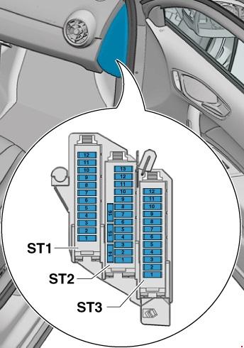
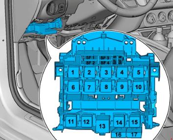
Location
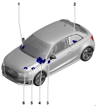
- Fuse holder D -SD-
- Fuse holder A -SA-
- Fuse holder C -SC-
- Fuse holder F -SF-
- Fuse holder B -SB-, Fuse holder H -SH-
- B -SB- Fuse Holders
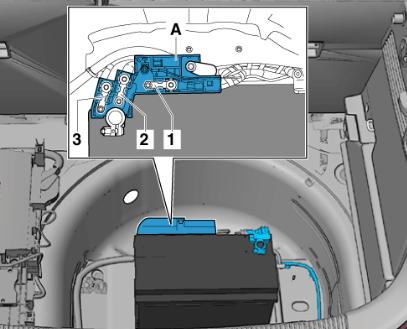
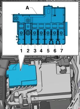
Fuse holder A -SA-
At the positive terminal of the battery (only on models with a battery in the trunk).
| No. | Amps [A] | Description |
| 1 | – | Empty |
| 2 | 110 | On-board power supply;
Engine component supply. |
| 3 | – | Empty |
Fuse holder B -SB-
For models with battery in the engine compartment
For models with a battery in the trunk
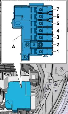
| No. | Amps [A] | Description |
| 1 | 175 | Alternator -C- |
| 2 | 40 | Low thermal power relay -J359-;
Supplemental air heating element -Z35-. |
| 3 | 110 1) | On-board power supply 1)
Supply of engine components 1) |
| 4 | 80 | Power Steering Controller -J500- |
| 5 | 50 2)
40 3) |
Radiator fan thermal switch -F18-;
Radiator fan controller -J293-. |
| 6 | 50 | Automatic light period control unit -J179- |
| 7 | 60 | High thermal power relay -J360-;
Battery monitor control unit -J367 1); Additional heating element -Z35-. |
| 1) for models with battery only in the engine compartment 2) no longer mounted, removed (model year 2011) 3) Modification introduced (model year 2011) |
||
Fuses in the electronics box in fuse holder B -SB- / fuse holder H -SH-.
In the electronics box in the left engine compartment.
Only for S1 version models, as of January 2014.
Only for models from November 2014 onwards.
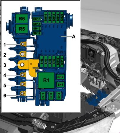
| No. | Amps [A] | Description |
| 1 | 110 4)
5 5) |
Onboard power supply 4);
Supply of engine components 4); Radiator Fan Controller -J293-. 5); Radiator Fan -V7 -5). |
| 2 | 250 | Alternator -C-; Voltage regulator -C1-. |
| 3 | – | Battery + |
| 4 | 80 | Power Steering Controller -J500- |
| 5 | 50 6) | Automatic glow period control unit -J179-. 6);
Glow plug 1 -Q10-; |
| 6 | 50 7)
– 8) – 9) |
Radiator fan control unit -J293-. 7);
Radiator Fan -V7- 7); – |
| 7 | 125 | On-board power supply 8);
Supply of engine components 8). |
| 4) Only for models with battery in the engine compartment, until October 2014. 5) only for models from November 2014 onwards 6) only for diesel engine models, as of November 2014 7) for models up to October 2014 8) for models with battery only in the engine compartment, starting in November 2014. 9) Fuse 5 in fuse holder B -SB5- connected, (see note). |
||
Fuses in the electronics box in fuse holder H -SH-.

| No. | Amps [A] | Description |
| 1 | 40 | Supplementary air heating element -Z35-, phase 1 |
| 2 | 30 | Radiator fan control unit -J293-;
Radiator fan control unit -V7-. |
| 3 | – | Empty |
| 4 | 40 | Supplemental air heating element -Z35-, step 2 |
| 5 | 40 | Supplemental air heating element -Z35-, phase 3 |
| 6 | 30 | Mechatronic unit for double-clutch transmission -J743- |
| 7 | 7,5 | Engine control unit -J623- |
| 8 | 20 | Wiper motor switching relay 1 -J368-;
Wiper motor switching relay 2 -J369-. |
| 9 | 5 | Battery Monitor Control Unit -J367- |
| 10 | 10 | Damping filter -C24- |
| 11 | – | Empty |
| 12 | 10 12)
15 13) 10) 11) |
Lambda probe heater -Z19-;
Lambda probe heater 1 after catalytic converter -Z29-. |
| 13 | 5 | Brake light switch -F- Clutch position transmitter -G476-. |
| 14 | 5 13)
10 10) 11) 12) |
Thermal cut-off switch for air conditioning system -F163-;
Fuel metering valve -N290- ; Oil pressure control valve -N428-; Cylinder head cooling valve -N489-; Coolant circulation pump -V50-; Coolant circulation pump -V55-; Charge air cooling pump -V188-; Auxiliary heating pump -V488-. |
| 15 | 5 | On-board power controller -J519-, T52c/34;
Engine controller -J623-, T91/67;T94/ Voltage stabilizer -J532-, T12aa/4. |
| 16 | 30 | Starter -B- |
| 17 | 15 12) 13)
30 10) 11) |
Engine control unit -J623- |
| 18 | 5 10) 11)
10 12) 13) |
Oil level and temperature sensor -G266-;
Fuel pump relay -J17-; Radiator fan controller -J293-; Low thermal power relay -J359-; High thermal power relay -J360-; Load pressure control solenoid valve -N75-; Turbocharger recirculation valve -N249-; Intake manifold flap valve -N316-; Oil pressure control valve -N428-; Coolant oil valve -N471-. |
| 19 | 7,5 10)
10 11) 13) 20 12) |
Motor current supply relay -J757-;
Fuel pressure control valve -N276-; Fuel metering valve -N290-; Injector 2 for cylinder 1 -N532-; Injector 2 for cylinder 2 -N533-; Injector 2 for cylinder 3 -N534-; Injector 2 for cylinder 4 -N535-; Actuator 1 for camshaft adjustment -F366-; Brake vacuum pump -V192-. |
| 20 | 5 10) 11)
10 13) 20 12) |
Automatic light period control unit -J179-;
Exhaust flap control unit -J883-; Crankcase ventilation heating element -N79-; Activated carbon filter solenoid valve 1 -N80-; Camshaft control valve 1 -N205-; Exhaust camshaft control valve 1 -N318-; Coolant circulation pump -V51-; Secondary air pressure transmitter 1 -G609-; Secondary air pressure transmitter 2 -G610-. |
| 10) only for models with 1.4 l diesel engine 11) only for models with 1.6 l diesel engine 12) only for models with a 1.0 l/1.4 l gasoline engine 13) only for models with a 1.8 l/2.0 l gasoline engine |
||
Fuse holder C -SC-
| No. | Amps [A] | Description |
| Black | ||
| 1 | 30 | Digital sound packaging control unit -J525- Voltage stabilizer -J532- Radio -R- |
| 2 | 40 | Heater control unit -J65-;
Relief relay contact X -J59-; Fresh air fan control unit -J126-; Fresh air fan control unit -V2-. |
| 3 | 20 | Lighters -U1-
12 V socket -U5- |
| 4 | 15 | Trailer detector control unit -J345- |
| 5 | 5 | Data bus diagnostic interface -J533- |
| 6 | 30 | Front passenger door controller -J387-;
Right rear door controller -J389-. |
| 7 | 30 | Driver door controller-J386-;
Left rear door controller -J388-. |
| 8 | 30 | Heated rear window relay -J9-;
Heated rear window -Z1-. |
| 9 | 25 | ABS control unit -J104- |
| 10 | 20 | On-board power control unit -J519- |
| 11 | 15 | High-pitched horn -H2-
Low-pitch horn -H7-; Horn relay -J413-. |
| 12 | 30 | On-board power control unit -J519- |
| brown | ||
| 1 | 5 | Alarm Horn -H12-;
Anti-theft alarm sensor -G578-. |
| 2 | 5 19) 16)
7,5 14) 15) 17) 18) 20) |
Terminal 30 voltage supply relay -J317-. 22);
Motronic power supply relay -J271-21 ) ; Engine Controller -J623-. |
| 3 | 5 | On-board power control unit -J519- |
| 4 | 5
15 23) |
ABS Controller -J104-;
Voltage Stabilizer 2 -J570-; Four-wheel drive controller -J492- 23). |
| 5 | – | Empty |
| 6 | 5 | Light sensor/combustion -G397- Cell phone antenna amplifier -R86-Tone pickup -R126-. Front roof module -WX3- |
| 7 | 15 21)
20 22) |
Fuel pump control unit -J538- 21)
Fuel pump relay -J17- 22) |
| 8 | 10 21) | Auxiliary coolant pump relay -J496-, until October 2014. |
| 9 | 5 | Electronic Steering Column Controller -J527- |
| 10 | 5 | Light switch -E1- |
| 11 | 10 | Climate control air conditioning controller -J255-;
Air conditioning system controller -J301-; Front passenger door controller -J387- (until April 2012); Right rear door controller -J389- (until April 2012); 16-pin connector -T16-, diagnostic connection. |
| 12 | 10 | Driver’s door controller -J386- (until April 2012);
Left rear door controller -J388- (until April 2012). |
| 13 | 10 | On-board power control unit -J519- |
| 14 | 20 | Relay for power socket -J807-, only for models without trailer socket |
| 15 | 30 | On-board power control unit -J519-. |
| 16 | 20 | Wiper motor switching relay 1 -J368-, until October 2014; Motor component current supply relay -J757-. 23) 24); Ignition coil 1 with output stage -N70-. 23) 24); Ignition coil 2 with output stage -N127-. 23 ) 24); Ignition coil 3 with output stage -N291-. 23) 24); Ignition coil 4 with output stage -N292-. 23) 24). |
| red | ||
| 1 | 5 19) 20)
20 15) 16) 17) |
Automatic light period control unit -J179-; Brake vacuum pump -V192-; |
| 2 | 10
5 34) |
Brake light switch -F- (until October 2011); Brake pedal switch -F63- (until October 2011); Auxiliary coolant pump relay -J496-; Lambda probe heater -Z19- (until October 2011); Lambda probe heater 1 after catalytic converter -Z29-, (until October 2011); Fuse 9 in fuse holder F -SF9-, (from November 2011 to October 2014); Fuse 10 in fuse holder F -SF10-, (November 2011 to; October 2014) ) ABS control unit -J104-, as of November 2011. |
| 3 | 5 18) 19) 20)
7,5 16 ) 15 14 ) 15) 17) |
Air mass meter -G70-, up to October 2014; Fuel pump relay -J17-, until October 2014; Low thermal power relay -J359-, until October 2014; High thermal power relay -J360-, until October 2014; Power supply to relay motor components -J757-, through October 2014; Fuel pressure control valve -N276-, until October 2014; Coolant circulation pump -V50-, until October 2014. |
| 4 | 15 14 ) 15) 17) 16)
25 18) 30 19 ) 20) |
Engine control unit -J623-;
Clutch position transmitter -G476-, until October 2011; Brake light switch -F-, until October 2011. |
| 5 | 20 18 )
15 19) 20) 20 14) 15 )1 7) 30 16) |
Ignition coil 1 with output stage -N70-, until October 2014; Ignition coil 2 with output stage -N127-, until October 2014; Ignition transformer -N152-, until October 2014; Fuel pressure control valve -N276-, until October 2014; Fuel metering valve -N290-, until October 2014; Ignition coil 3 with output stage -N291-, until October 2014; Ignition coil 4 with output stage -N292-, until October 2014. |
| 6 | 10 20 16) |
Radiator fan control unit -J293-, until October 2014; Relay heater element -J925-, until October 2014; Charge pressure control solenoid valve -N75-, until October 2014; Activated carbon filter 1 solenoid valve -N80-, until October 2014; Exhaust camshaft control valve 1 -N205-, until October 2014; Turbocharger recirculation valve -N249-, until October 2014; Intake manifold flap valve -N316-, until October 2014; Exhaust camshaft control valve 1 -N318-, until October 2014; Exhaust gas recirculation switch valve -N345-, until October 2014; Oil pressure control valve -N428-, until October 2014. Cam adjuster; exhaust for cylinder 2 -N587-, until October 2014; Cam adjuster for cylinder 2 intake cam -N583-, to October 2014. Cylinder input cam adjuster 3 -N591-, for October 2014; Cylinder 3 exhaust cam adjuster -N595-, to October 2014; Exhaust gas recirculation pump -V400-. |
| 7 | 5 | CD Switch -R41- |
| 8 | 5 | Internet access control unit-J666-;
Smart card reader control unit-J676-; Radio -R-; TV Tuner -R78-. |
| 9 | 5 | Control unit on instrument panel -J285- |
| 10 | 5 | Relay for automatic anti-glare interior mirror -J910-;
Automatic anti-glare interior mirror -Y7-. |
| 11 | 7,5 32)
15 33) |
Radio -R- Control unit for information electronics 1 -J794- |
| 12 | 5 | Display for front information display and operation unit control unit -J685-. |
| 14) only for models with 1.2 l gasoline engine 15) only for models with 1.4 liter (90 kW) gasoline engine 16) only for models with a 1.4 liter (103 kW) gasoline engine 17) for models with a 1.4 liter (136 kW) gasoline engine only 18 ) only for models with a 2.0-liter gasoline engine 19) only for models with a 1.6 liter diesel engine 20) only 2.0 l diesel engine models 21) only gasoline engine models 22) only diesel models 23) For models with a 2.0 liter gasoline engine from January 2014 24) for models with a 1.8-liter gasoline engine from November 2014 32) only for models with MMI 33) only for models without MMI 34) From November 2011 |
||
Fuse Holder D -SD-
| No. | Amps [A] | Description |
| Black | ||
| 1 | 7,5 | ESL control unit -J764- |
| 2 | 20 | Trailer detector control unit -J345- |
| 3 | 20 | Trailer detector control unit -J345- |
| 4 | 30 7,5 |
Mechatronic unit for dual clutch transmission -J743-, until October 2014; Electronically controlled damping control unit -J250-, from January 2014. |
| 5 | 30 | Headlight washer relay system -J39-;
Headlight washer system pump -V11-. |
| 6 | 5 | Interface control unit for vehicle location system -J843- |
| 7 | 7,5 | Entry authorization control unit and startup -J518-. |
| 8 | 15 | Mechatronic assembly for dual-clutch transmission -J743-, by October 2014. |
| 9 | 20 | Sliding roof motor -V1- |
| 10 | 7,5 | Gearshift lever sensor controller -J587- |
| 11 | 15 35) | Motor component current supply relay -J757-, through October 2014; Fuel pressure control valve -N276-, until October 2014. |
| 12 | – | Empty |
| brown | ||
| 1 | 5 | Reversing light switch -F4-;
Shift lever sensor controller -J587-; Dual-clutch mechatronic transmission module -J743-. |
| 2 | 10 | High pressure sensor -G65-;
Oil level and temperature sensor -G266-; Air conditioning system controller -J301-; Plug-in relay -J807-; Automatic anti-glare interior mirror -Y7-; 16-pin connector -T16-, diagnostic connector. |
| 3 | 5 | Data bus diagnostic interface -J533- |
| 4 | 5 | Heater control unit -J65-;
Material sound control unit -J869-. |
| 5 | 7,5 | Light switch -E1-;
Starter relay 1 -J906-; Voltage stabilizer -J532-; Start relay 2 -J907-; Relay for automatic anti-glare interior mirror -J910-; Front left reflector -MX1-; Front right reflector -MX2-. |
| 6 | 5 | Light switch -E1- |
| 7 | 5 | ABS Controller -J104-, until October 2014 Voltage stabilizer 2 -J570-, until October 2014 Electronically controlled damping controller -J250-, as of January 2014 |
| 8 | 5 | Heated driver’s seat adjuster -E94-;
Heated front passenger seat adjuster -E95-; Hazard warning light button -E229-; Heated rear window button -E230-; TCS and ESP button -E256-; Parking aid button -E266-; Tire pressure monitor display button -E492-; Start/Stop button -E693-; Trailer sensor control unit -J345-; Left side washer jet heating element -Z20-; Correct element of water-jet washer -Z21-. |
| 9 | 5 | Power steering controller -J500- |
| 10 | 5 36)
7,5 37) |
Air mass meter -G70-;
Fuel pump controller -J538-; Crankcase breather heating element -N79-. |
| 11 | 5 | Airbag Controller -J234-;
Front passenger front airbag deactivation warning light -K145-. |
| 12 | 5 | Parking assist control unit -J446- |
| 13 | 5 | Control unit for headlight range control -J431- |
| 14 | 30 | Seat heating control unit -J882- |
| 15 | 15 | Rear wiper motor -V12- |
| 16 | 5 | Engine control unit -J623-; Air mass meter -G70-. |
| red | ||
| 1 | – | Emptiness |
| 2 | – | Emptiness |
| 3 | 10 | Four-wheel drive controller -J492- , gradual withdrawal |
| 4 | – | Emptiness |
| 5 | – | Emptiness |
| 6 | – | Emptiness |
| 7 | – | Emptiness |
| 8 | – | Emptiness |
| 9 | – | Emptiness |
| 10 | 5 10 |
Special vehicle control unit -J608- |
| 11 | – | Emptiness |
| 12 | – | Emptiness |
| 35) only for models with 2.0 l gasoline engine 36) only for models with gasoline engine 37) only for diesel engine models |
||
Fuse holder F -SF-
| No. | Amps [A] | Description |
| 1 | 40 | Voltage Stabilizer -J532- |
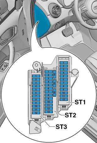
| 2 | 50 | Power fuse holder 1 -ST1- in fuse holder D -SD-. |
| 3 | 40 | Voltage supply relay terminal 15 -J329- |
| 4 | 40 | ABS control unit -J104- |
| 5 | 5 | Voltage Stabilizer 2 -J570-, degressive |
| 6 | 5 | On-board power control unit -J519-;
Voltage stabilizer -J532-; Voltage stabilizer 2 -J570-, step-down; Motor control unit -J623-. |
| 16 | 10 | Brake light switch -F- (from November 2011 to October 2014) Clutch position transmitter -G476- (from November 2011 to November 2014) |
| 17 | 5 | Lambda probe heater -Z19- (November 2011 to October 2014) Lambda probe heater 1 after catalytic converter -Z29- (November 2011 to November 2014) |