Volvo S60 (2017) – fuse box diagram
Year of manufacture: 2017.
Fuses Fuses (power outlets) in the Volvo S60 is fuse number 22 (12-volt outlets in the tunnel console) in fuse holder “A” under the glove box and fuse number 7 (rear 12-volt outlet) in the trunk fuse holder.
Fuse box location
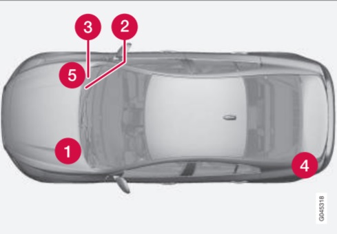
1) Engine compartment
2) Under glove compartment fuse box A (general fuses)
3) Under glove box fuse box B (control module fuses)
It is located under the headliner.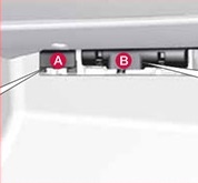
4) Luggage compartment
Located behind the upholstery on the left side of the luggage compartment.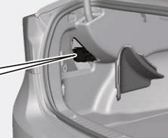
5) Cold zone in engine compartment (Start/Stop only).
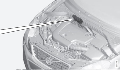
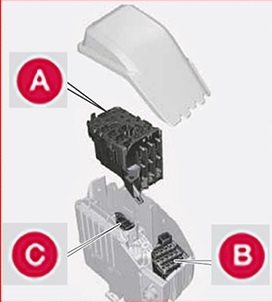
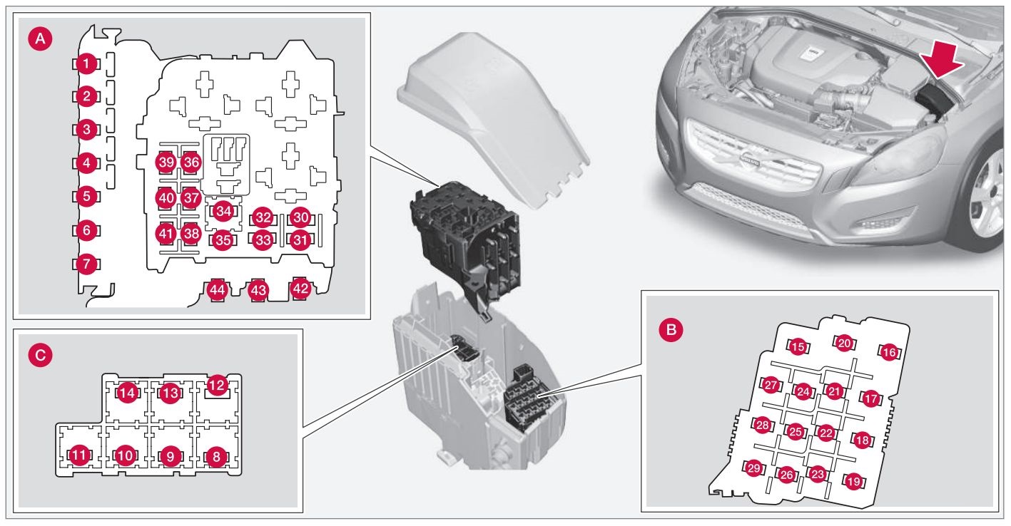
Fuses – engine compartment
A – Engine compartment cover
B – Front Engine Compartment
C – Lower Engine Compartment
| No. | Description | Amps [A] |
| 1 | Automatic circuit breaker: central electrical module under the glove box A | 50 |
| 2 | Automatic switch: central electrical module under the glove box | 50 |
| 3 | Automatic switch: central electrical module in trunk A | 60 |
| 4 | Automatic circuit breaker: central electrical module under the glove box A | 60 |
| 5 | Automatic circuit breaker: central electrical module under the glove box A | 60 |
| 6 | – | – |
| 7 | – | – |
| 8 | Front windshield*, driver’s side | 40 |
| 9 | Cleaners | 30 |
| 10 | – | – |
| 11 | Air conditioning system fan A | 40 |
| 12 | Front windshield*, passenger side | 40 |
| 13 | ABS Pump | 40 |
| 14 | ABS Valves | 20 |
| 15 | Headlight Washers | 20 |
| 16 | Active leveling of corner lights * | 10 |
| 17 | Central electrical module (under the glove box) | 20 |
| 18 | ABS | 5 |
| 19 | Adjustable steering effort * | 5 |
| 20 | Engine control module (ECM);
Transmission; SRS. |
10 |
| 21 | Heated windscreen washer nozzles* | 10 |
| 22 | – | – |
| 23 | Lighting Panel | 5 |
| 24 | – | – |
| 25 | – | – |
| 26 | – | – |
| 27 | Relay Coils | 5 |
| 28 | Additional lights * | 20 |
| 29 | Horn | 15 |
| 30 | Relay coils;
Engine control module (ECM). |
10 |
| 31 | Control module – automatic transmission | 15 |
| 32 | A/C compressor (not applicable to 4-cylinder engines) | 15 |
| 33 | A/C relay coils;
Relay coils in the cold area of the engine compartment for Start/Stop. |
5 |
| 34 | Start Relay A | 30 |
| 35 | Engine control module (4-cylinder engines);
Ignition coils (5-cylinder engines). |
20 |
| 36 | Engine control module (4-cylinder engines) | 20 |
| Engine control module (5-cylinder engines) | 10 | |
| 37 | 4-cylinder engines:
air mass gauge, thermostat, EVAP Valve |
10 |
| 5-cylinder engines:
injection system, engine control module. |
15 | |
| 38 | A/C Compressor (5-cylinder engines);
Engine valves; Oil level sensor (5-cyl. only). |
10 |
| Engine valves;
Oil pump; Centrally heated lambda probe (4-cylinder engines). |
15 | |
| 39 | Heated lambda probes front and rear (4-cylinder engines);
EVAP valve (5-cylinder engines); Heated oxygen sensors (5-cylinder engines). |
15 |
| 40 | Oil pump;
Crankcase heater; Coolant pump (5-cylinder engines). |
10 |
| Ignition coils (4-cylinder engines) | 15 | |
| 41 | Fuel leak detection (5-cylinder engines);
Radiator shutter control module (5-cylinder engines). |
5 |
| Fuel leak detection;
Air conditioning solenoid (4-cylinder engines). |
7,5 | |
| 42 | Coolant pump (4-cylinder engines) | 50 |
| 43 | Cooling Fan | 60 or 80 (4-cylinder engines) |
| 60 (5-cylinder engines) | ||
| 44 | Power steering | 100 |
| * – Option / optional equipment, for more information see Introduction | ||
| A – This position is not used on vehicles with the optional Start / Stop function | ||
Fuses – glovebox

Box fuses A General fuses
Fuse Box B : Fuses control module
Items: fuse box A
| No. | Description | Amps [A] |
| 1 | Information switch and fuse system circuit breaker 16-20 | 40 |
| 2 | Windshield washers | 25 |
| 3 | – | – |
| 4 | – | – |
| 5 | – | – |
| 6 | Keyless driving * (door handles) | 5 |
| 7 | – | – |
| 8 | Driver’s door control | 20 |
| 9 | Passenger door controls | 20 |
| 10 | Controls on the right rear passenger door | 20 |
| 11 | Controls on the left rear passenger door | 20 |
| 12 | Keyless driving * | 7,5 |
| 13 | Driver’s seat with drive * | 20 |
| 14 | Electrically operated front passenger seat * | 20 |
| 15 | – | – |
| 16 | Infotainment system display | 5 |
| 17 | Audio-navigation system:
amplifier, SiriusXM satellite radio ™*. |
10 |
| 18 | Census control module | 15 |
| 19 | Bluetooth car handsfree kit | 5 |
| 20 | – | – |
| 21 | Opening ceiling actuator*;
Illumination at door opening; Air conditioning system sense. |
5 |
| 22 | 12 V sockets on the console between the seats | 15 |
| 23 | Heated rear seat* (passenger side) | 15 |
| 24 | Heated rear seat* (driver’s side) | 15 |
| 25 | – | – |
| 26 | Heated front passenger seat* | 15 |
| 27 | Heated driver’s seat* | 15 |
| 28 | Parking assistant*
Blind spot information system (BLIS)*; Parking camera*. |
5 |
| 29 | Control module for four-wheel drive * | 15 |
| 30 | Active chassis system * | 10 |
Items: fuse box B
| No. | Description | Amps [A] |
| 1 | – | – |
| 2 | – | – |
| 3 | Additional front lighting;
Driver’s door glass control; Electrically adjustable seats*. |
7,5 |
| 4 | Dashboard | 5 |
| 5 | Adaptive cruise control;
Collision warning*. |
10 |
| 6 | Supplemental lighting;
Rain sensor *; HomeLink® wireless control system*. |
7,5 |
| 7 | Steering wheel module | 7,5 |
| 8 | Central shutdown:
fuel filler door |
10 |
| 9 | Electrically heated steering wheel* | 15 |
| 10 | Electrically Heated Windscreen*[19659309 | 15 |
| 11 | Boot opening | 10 |
| 12 | Rear seat headrests* electrically folding | 10 |
| 13 | Fuel Pump | 20 |
| 14 | Control panel for air conditioning system | 5 |
| 15 | – | – |
| 16 | Alarm, on-board diagnostic system | 5 |
| 17 | Satellite Radio*;
Audio system amplifier. |
10 |
| 18 | Airbag system;
Passenger weight sensor. |
10 |
| 19 | Collision Warning System*[19659336 | 5 |
| 20 | Accelerator pedal sensor;
Automatic mirror dimming function; Heated rear seats*;[19659340 |
7,5 |
| 21 | – | – |
| 22 | Stoplights | 5 |
| 23 | Ceiling actuator*. | 20 |
| 24 | Immobilizer | 5 |
Fuses – load compartment / luggage compartment

| No. | Description | Amps [A] |
| 1 | Electric parking brake (left side) | 30 |
| 2 | Electric parking brake (right side) | 30 |
| 3 | Heated rear window | 30 |
| 4 | Towing socket 2* | 15 |
| 5 | – | – |
| 6 | 12 V socket in the trunk | 15 |
| 7 | – | – |
| 8 | – | – |
| 9 | – | – |
| 10 | – | – |
| 11 | Towing socket 1* | 40 |
| 12 | – | – |
Fuses – cold zone of engine compartment (Start / Stop only) – Option on 4-cylinder engines.

| No. | Description | Amps [A] |
| A1 | Automatic circuit breaker: central electrical module in the engine compartment | 175 |
| A2 | Automatic circuit breaker: fuse box under glove compartment, central electrical module in trunk | 175 |
| 1 | – | – |
| 2 | Breaker: fuse box B under the glove box | 50 |
| 3 | Breaker: fuse box A under the glove compartment | 60 |
| 4 | Breaker: fuse box A under the glove compartment | 60 |
| 5 | Automatic switch: central electrical module in the trunk | 60 |
| 6 | Air conditioning system fan | 40 |
| 7 | – | – |
| 8 | – | – |
| 9 | Startup Relay | 30 |
| 10 | Internal diode | 50 |
| 11 | Auxiliary Battery | 70 |
| 12 | Central electrical module: auxiliary battery reference voltage, auxiliary battery charge point | 15 |