2010, 2011, 2012, 2013, 2014.
Cigarette lighter (power outlet) merges into Honda Insight is fuse number 13 in the instrument panel fuse box.
Passenger compartment
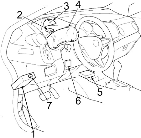
- Fuse box
- Control unit for the tire pressure monitoring system (TPMS)
- Indicator control module
- Indicator control module
- Supplementary Restraint System (SRS) Unit
- Electronic Power Steering (EPS) Control Unit
- Hatch release actuator relay
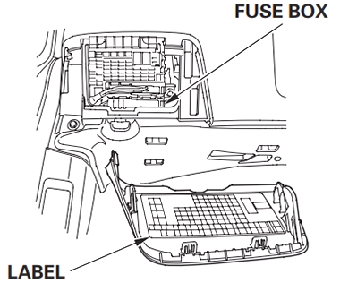
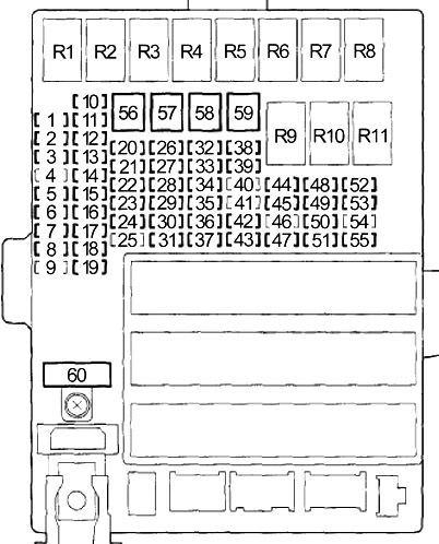
Instrument panel fuse box diagram
The internal fuse box is located behind the instrument panel on the driver’s side. The label is affixed to the back of the cover. To view the label on the internal fuse box, remove the cover by pulling it toward you while holding the lower center section of the cover.
| Number | Amps [A] | Description |
|---|---|---|
| 1 | 15 | Audio/navigation unit (with navigation), audio unit (without navigation), cargo area lighting, ceiling lighting, data link connector (DLC), instrument control unit, keyless immobilizer control unit, HandsFreeLink control unit, individual map lighting, integrated multiplex control unit (MICU) (+B BACK UP), engine control module (MCM) |
| 2 | 7,5 | Control unit for tire pressure monitoring system (TPMS) |
| 3 | 20 | Main window switch |
| 4 | – | – |
| 5 | 10 | Back-up Light, Multiplex Integrated Control Unit (MICU) |
| 6 | 10 | Supplementary Restraint System (SRS) unit |
| 7 | 10 | Powertrain Control Module – PCM (VBSOL) |
| 8 | 7,5 | Occupant detection system module (ODS), front passenger front airbag cut-off indicator, supplemental restraint system module (SRS) |
| 9 | – | – |
| 10 | 7,5 | A/C compressor clutch relay, fan motor relay, A/C unit, fan control relay (A/C diode), optional connector, power mirror switch, radiator fan relay (A/C diode), rear window defroster relay, recirculation control motor |
| 11 | 7,5 | EPS control unit (IG1), VSA modulator control unit (IG1), yaw acceleration sensor (with VSA), ABS modulator control unit (MTR) (without VSA) |
| 12 | 10 | DC-DC converter, fuel vapor absorber vent valve (EVAP), powertrain control module – (idle switch), mass air flow (MAF) sensor, secondary heated oxygen (HO2S) sensor |
| 13 | 20 | Accessory power socket |
| 14 | 7,5 | Audio/navigation unit (with navigation), audio unit (without navigation), key lock solenoid, HandsFreeLink control unit, MICU (ACC), optional connector |
| 15 | 7,5 | Daytime running lights, Multiplex Integrated Control Unit (MICU) |
| 16 | 10 | Rear wiper motor |
| 17 | 20 | Front passenger window motor, front passenger window switch |
| 18 | 20 | Right rear window motor, main window switch, right rear window switch light |
| 19 | 20 | Left rear window motor, main window switch, left rear window switch |
| 20 | 15 | Fuel pump (PGM-FI master relay No. 2 (2012-2014)), immobilizer control unit-keyless, powertrain control module-PCM (IG1) (2012-2014) |
| 21 | 15 | Washer motor, Multiplex Integrated Control Unit (MICU) |
| 22 | 7,5 | Electrical load sensor (ELD), gauge control module, integrated Multiplex control unit – MICU (IG1 meters), engine control module (MCM), gear locking solenoid, tire pressure monitoring system (TPMS) control unit |
| 23 | 10 | Turn signal/danger relay, Multiplex Integrated Control Unit (MICU) |
| 24 | 10 | Brake pedal position switch, high-mounted brake light, left brake light, right brake light, horn relay, integrated multiplex control unit (MICU), powertrain control module (PCM) |
| 25 | – | – |
| 26 | 10 | Air/fuel ratio (A/F) sensor, evaporative emission control (EVAP), canister vent valve, fuse: № 31 (7.5 A) |
| 27 | 30 | Motorized door lock, integrated multiplex control unit (MICU) |
| 28 | 20 | Reflector (main), Multiplex Integrated Control Unit (MICU) |
| 29 | 10 | Parking light, Multiplex Integrated Control Unit (MICU) |
| 30 | 30 | Radiator fan motor (radiator fan relay), A/C condenser fan motor (fan control relay) (2012-2014) |
| 31 | 7,5 | A/C condenser fan relay (A/C system diode B) |
| 32 | 10 | Right Headlight (Low beam) |
| 33 | 20 | Ignition coil relay, fuses (engine compartment): №1 (15 A), 2 (15 A) |
| 34 | 10 | Left Headlight (Low beam) |
| 35 | 15 | Front passenger door lock actuator, right rear door lock actuator |
| 36 | 15 | Driver door lock actuator, left rear door lock actuator |
| 37 | 30 | modulator-control unit ABS (without VSA), modulator-control unit VSA |
| 38 | 15 | Driver’s door lock actuator |
| 39 | 15 | Crankshaft position sensor (CKP), crankshaft position sensor (CMP), electronic throttle control relay (ETCS), injectors, powertrain control module – PCM (IGP), PGM-FI #1 main relay, PGM-FI #2 main relay (fuel pump) |
| 40 | – | – |
| 41 | – | – |
| 42 | 10 | Motor Control Module (MCM), MCM Relay No. 1, MCM Relay No. 2 |
| 43 | 7,5 | A/C compressor (A/C compressor clutch relay) |
| 44 | 7,5 | Start relay, traction unit control module – PCM (STS) |
| 45 | 7,5 | Manhole opening actuator, manhole opening actuator |
| 46 | – | – |
| 47 | 30 | A/C condenser fan motor (A/C condenser fan relay), radiator fan motor (fan control relay) (2010-2011) |
| 48 | 10 | Left Headlight (High beam) |
| 49 | 15 | Front passenger door lock actuator, right rear door lock actuator |
| 50 | 15 | Left rear door lock actuator |
| 51 | 10 | Right Headlight (High beam) |
| 52 | 15 | Electronic Throttle Control System (ETCS), Power Control Module – PCM (IG1ETCS) |
| 53 | 10 | Intelligent power unit (IPU) Fan module (motor control module (MCM) relay No. 2), motor inverter module (MPI) (motor control module (MCM) relay No. 2) |
| 54 | – | – |
| 55 | 10 | Left power mirror fog, right power mirror fog |
| 56 | 30 | Front wiper, Multiplex Integrated Control Unit (MICU) |
| 57 | 30 | Blower motor (blower motor relay) |
| 58 | 30 | Modulator-control unit ABS (without VSA), modulator-control unit VSA |
| 59 | 30 | Without electric mirror demister: rear window demister (lower rear window demister, upper rear window demister, noise reduction capacitor) |
| 40 | With electric mirror defroster: Rear window defroster relay (lower rear window defroster, upper rear window defroster, noise reduction capacitor, fuse: №55 (10 A)) | |
| 60 | 50 | Ignition Switch |
| 30 | Headlight Washer | |
| R1 | Supply of windows | |
| R2 | Fan motor | |
| R3 | Air/Fuel Ratio Sensor (A/F) | |
| R4 | Lighting | |
| R5 | Ignition Coil | |
| R6 | PGM-FI Main №1 | |
| R7 | Electronic Throttle Control System (ETCS) | |
| R8 | Rear window defogger | |
| R9 | Driver’s door unlocking | |
| R10 | Initial cut | |
| R11 | – | |
Engine compartment
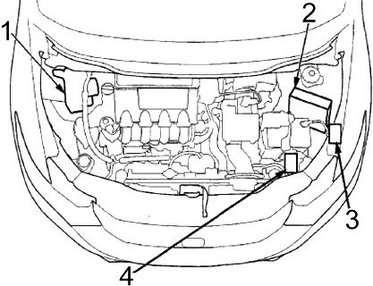
- ABS modulator-control unit (without VSA), VSA modulator-control unit
- Powertrain Control Module (PCM)
- Relay box №1
- Relay box №2
Diagram of the fuse box in the engine compartment
The main fuses under the engine compartment cover are located on the positive terminal of the battery. To open it, press the tabs as shown. These fuses cannot be repaired; replace the battery terminal fuse box as an assembly.
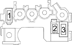
| Number | Amps [A] | Description |
|---|---|---|
| 1 | 100 | DC-DC converter, lighting relay, windshield relay, driver door release relay, fuses: № 1, 2, 3, 9, 17, 18, 19, 25, 26, 27, 28, 29, 30, 32, 33, 34, 37, 38, 39, 40, 41, 42, 43, 45, 46, 47, 52, 53, 57, 58, 59, 60 |
| 2 | 60 | Electronic Power Steering (EPS) |
| 3 | 20 | Fuses: 23, 24 |
Relay box 1
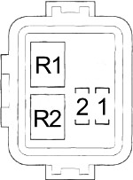
| Number | Amps [A] | Protected ingredient |
|---|---|---|
| 1 | 15 | Exhaust side ignition coils |
| 2 | 15 | Intake Side Ignition Coils |
| R1 | Fan Control | |
| R2 | PGM-FI Main №2 (Fuel pump) | |
Relay box 2
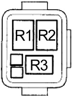
| Number | Courier |
|---|---|
| R1 | A/C condenser fan |
| R2 | Radiator Fan |
| R3 | A/C compressor clutch |