Volkswagen Passat B8 – fuse box diagram
Year of manufacture: 2015, 2016, 2017, 2018, 2019, 2020, 2021.
Cigarette lighter fuse (power outlet) in a Volkswagen Passat B8 Is fuse 40 in the fuse box in the passenger compartment.
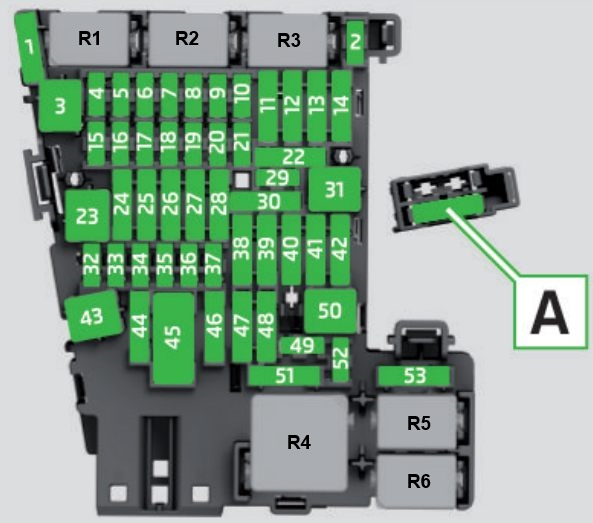
Passenger compartment
Located under the dashboard, on the driver’s side, behind the glove box.
| No. | Amps [A] | Description |
| 1 | 30A | Heater control unit with reducing agent -J891-. |
| 2 | 10 A | Electronic Steering Column Controller -J527- |
| 3 | – | – |
| 4 | 7.5A/10A | Alarm horn -H12- |
| 5 | 5A / 7.5A | Data Bus Diagnostic Interface -J533- |
| 6 | 5A / 7.5A | Gear shift lever -E313- |
| 7 | 10 A | Heater and air conditioning controls -EX21-; Rear air conditioning control and display unit -E265-; Remote control receiver for auxiliary coolant heater -R149-; rear window heater relay -J9-; Analog clock -Y-; Tire pressure monitoring system control unit -J502-. |
| 8 | 7.5A/10A | Rotary light switch -EX1-;
Electromechanical parking brake button -E538-; Rain and light sensor -G397-; Diagnostic connector -U31-; Anti-theft alarm sensor -G578-; |
| 9 | 5A / 7.5A | Electronic Steering Column Controller -J527- |
| 10 | 7.5A/10A | Front information display and operating unit control unit -J685-; Head-up display control unit -J898-. |
| 11 | 40A | On-board power control unit -J519-. |
| 12 | 20A | Electronic information control unit 1 -J794-; Navigation system control unit -J856- 1). |
| 13 | 25A | Front Left Seat Belt -NX10- |
| 14 | 40A | Fresh Air Fan Control Unit -J126- |
| 15 | 10 A | Electronic steering column lock control unit -J764- |
| 16 | 7,5A | Two-way signal booster for mobile phones/data services -J984-; USB 1 charging socket -U37-; Clipboard with cell phone interface -R265-; USB hub -R293-. |
| 17 | 7,5A | -KX2- panel panel insert Alarm link module control unit and communication unit -J949-. |
| 18 | 7,5A | Control unit for the upper chamber -J928-;
Back cover bracket -EX37-; Rear Top Camera -R246-. |
| 19 | 7,5A | Interface with the input and commissioning system -J965- |
| 20 | 7.5A/10A/15A | Reducing agent measuring system relay -J963-; Vacuum pump relay -J318-. |
| 21 | 15A | Four Wheel Drive Controller -J492- |
| 22 | 15A | Trailer detector control unit -J345- |
| 23 | 20A / 30A | Controller for sliding roof adjustment -J245- |
| 24 | 40A | On-board power control unit -J519-. |
| 25 | 30A | Driver’s door controller-J386-; Driver’s rear door controller -J926-. |
| 26 | 30A | On-board power control unit -J519-. |
| 27 | 30A | On-board power control unit -J519-. |
| 28 | 25A | Trailer detector control unit -J345- |
| 29 | 5A | Remote start system relay -J471- |
| 30 | 10 A | Remote start system relay -J471- |
| 31 | 30A | Back Cover Controller -J605- |
| 32 | 10 A | Front camera for driver assistance systems -R242-;
Adaptive cruise control unit -J428-; Park assist control unit -J446-; Lane change assistant control unit -J769-; Lane change assistant control unit 2 -J770-. |
| 33 | 5A / 7.5A | Airbag control unit -J234- |
| 34 | 7,5A | Interior mirror -EX5-;
Socket relay -J807-; Reversing light switch -F4-; Coolant circuit pressure sensor -G805-; Air quality sensor -G238-; Instrument panel center switch module -EX22-; Center switch module 1 in center console -EX23-; Material sound control unit -J869-; Electromechanical parking brake button -E538-. |
| 35 | 7,5/10A | Diagnostic connection -U31- |
| 36 | 5A / 7.5A | Front right reflector -MX2- |
| 37 | 5A / 7.5A | Front left headlight -MX1-. |
| 38 | 25A | Trailer detector control unit -J345- |
| 39 | 30A | Front passenger door controller -J387-;
Rear passenger door controller -J927-. |
| 40 | 20A | 12 V socket -U5-;
12 V socket 2 -U18-; 12 V socket 3 -U19-. |
| 41 | 25A | Right Front Seat Belt -NX11- |
| 42 | 40A | On-board power control unit -J519-. |
| 43 | 40A | Digital Sound Package Control Unit -J525- |
| 44 | 15A | Trailer detector control unit -J345- |
| 45 | 15A | Driver’s seat adjustment controller -J810-;
Left front seat fan 1 -V514-; Left front seat backrest fan 1 -V512-. |
| 46 | 30A | DC/AC converter with socket, 12 V – 230 V -U13-. |
| 47 | – | – |
| 48 | – | – |
| 49 | 5A / 7.5A | Clutch position transmitter -G476-; Starter relay 1 -J906-; Start Relay 2 -J907-. |
| 50 | 40A | Back Cover Controller -J605- |
| 51 | 25A | Rear air conditioning operating and display panel -E265- |
| 52 | 15A | Electronically controlled damping control unit -J250-. |
| 53 | 30A | Heated Rear Window Relay -J9- |
The following fuses are also located in the fuse box holder:
| A | 15A | Operation panel for adjusting the right front seat -EX34-;
Right front seat fan 1 -V518-; Right front front seat backrest fan 1 -V516-. |
| B | 5A | Remote start system relay -J471- |
| C | 7,5A | USB charging socket 1 -U37- |
| R1 | Remote start system relay -J471- |
Relay
- Relay R1 for reducing agent dosing system -J963-.
- R2 –
- R3 –
- R4 Voltage supply relay terminal 15 -J329-.
- R5 Heated rear window relay -J9-.
- R6 Power socket relay -J807-
Motor compartment
It is located on the left side next to the battery and is covered by a protective cover. It consists of 2 sections: a communication section with fuses and relays, and a section for high power fuses.
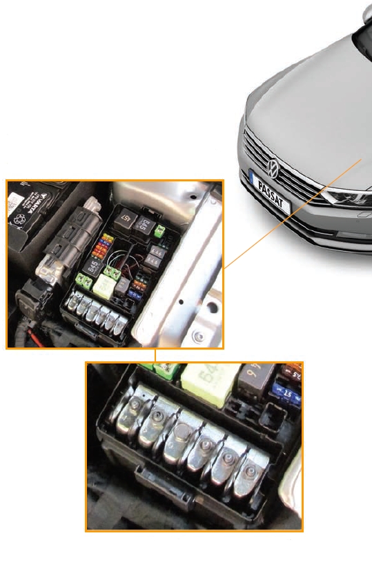
Diagram of the fuse box
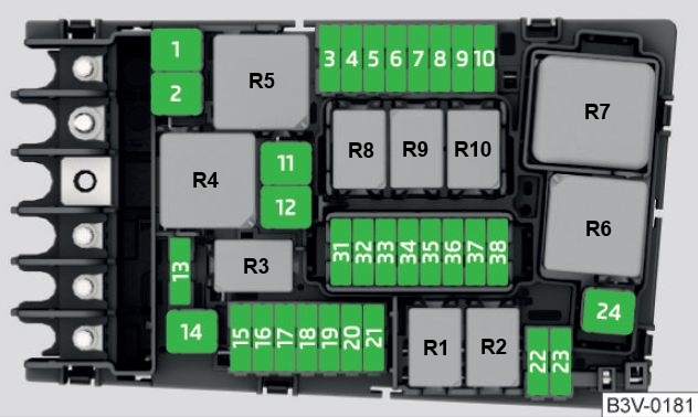
| No. | Amps [A] | Description |
| 1 | 25A | ABS control unit -J104- |
| 2 | 40A / 60A | ABS Controller -J104-;
ABS Hydraulic Pump -V64-. |
| 3 | 15A 30A |
Motor/motor control unit -J623- |
| 4 | 5A / 7.5A / 10A | Radiator Fan -VX57-;
High thermal power relay -J360-; Low thermal power relay -J359-; Oil pressure control valve -N428-; Turbocharger air recirculation valve -N249-; Intake manifold flap valve -N316-; Piston cooling nozzle control valve -N522-; Oil level and temperature sensor -G266-; Turbine diverter valve -N529-; Engine component current supply relay -J757-. |
| 5 | 10 A | Fuel pressure control valve -N276-;
Fuel metering valve -N290-; Engine component current supply relay -J757-; Turbine switching valve -N529-. |
| 6 | 5A / 7.5A | Brake Light Switch -F- |
| 7 | 7.5A/10A/15A | Charge air cooling pump -V188-;
Transmission cooling valve -N488-; Coolant shutoff valve -N82-; Auxiliary heating pump -V488-; Cylinder head cooling valve -N489-; Oil pressure control valve -N428-; Leak detection in fuel tank controller -J909-. |
| 8 | 15A | Lambda probe 1 before catalytic converter -GX10-; Lambda probe 1 after catalytic converter -GX7-; NOx sensor controller -GX30-; NOx sensor controller 2 -J881-. |
| 9 | 5A / 10A | Exhaust flap controller -J883-;
Exhaust flap controller 2 -J945-; Automatic brightness period controller -J179-; Crankcase ventilation heating element -N79-; Air mass meter -G70-; Auxiliary heating pump -V488-; Activated carbon filter solenoid valve 1 -N80-; Exhaust camshaft control valve 1 -N318-; Exhaust camshaft control valve 1 -N205-. |
| 10 | 15A / 20A | Fuel pump control unit -J538- |
| 11 | 40A / 50A | Auxiliary Air Heating Element -Z35- |
| 12 | 40A | Auxiliary Air Heating Element -Z35- |
| 13 | 30A | Auxiliary hydraulic pump 1 for gearbox oil -V475-. |
| 14 | 40A | Heated windscreen relay -J47- |
| 15 | 15A | Horn Relay -J413- |
| 16 | 20A | Motor component current supply relay -J757-. |
| 17 | 7,5A | Motor control unit -J623-;
ABS control unit -J104-; Heated windshield relay -J47-. |
| 18 | 5A / 7.5A | Battery monitor control unit -J367-;
Data bus diagnostic interface -J533-. |
| 19 | 30A | Wiper motor control unit -J400- |
| 20 | 10 A | Alarm horn -H12- |
| 21 | 30A | Heated windscreen relay 2 -J611- |
| 22 | 5A / 7.5A | Motor/motor control unit -J623- |
| 23 | 30A | Starter -B- |
| 24 | 40A | Auxiliary Air Heating Element -Z35- |
| 31 | – | – |
| 32 | – | – |
| 33 | 30A | Heated windscreen relay 2 -J611- |
| 34 | 30A | Heated windscreen relay 2 -J611- |
| 35 | 30A | Wiper motor control unit -J400- |
| 36 | – | – |
| 37 | 30A | Auxiliary heater control unit -J364- |
| 38 | – | – |
Courier
- R1 Starter Relay 1 -J906-
- R2 Starter Relay 2 -J907-
- R3 horn relay -J413-
- R4 High Thermal Power Relay -J360-
- R5 main relay -J271- (gasoline) / Terminal 30 supply voltage relay -J317- (diesel)
- R6 Automatic light period control unit -J179- (petrol)
- R7 Low thermal power relay -J359- (diesel)
- R8 Power supply relay for engine components -J757- (2.0l gasoline engine)
- R9 Heated windshield relay -J47-.
- R10 Heated windshield relay 2 -J611-.