Volkswagen Beetle A5 – Fuse box diagram
Year of manufacture: 2011, 2012, 2013, 2014, 2015, 2016, 2017, 2018, 2019.
Cigarette lighter fuse (power outlet) in the Volkswagen Beetle A5 Is a 30 (20A) fuse in the fuse box in the passenger compartment.
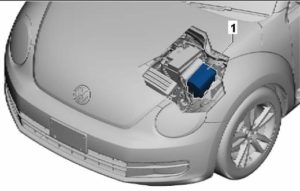
Engine compartment
Located next to the battery, under the protective cover.
| No. | Description |
| 1 | Reservation |
| 2 | 20/30A – Motor control unit |
| 3 | 5A – Radiator Fan Control Unit |
| 4 | 15A – Lambda Probe |
| 5 | 10A – Lambda probe;
Electric fuel pump relay; Heating resistor relay; Load pressure limiting solenoid valve; Crankcase ventilation heating resistor, valve 1; Variable valve timing; Turbocharger bypass valve; Intake manifold handle valve; Recirculating radiator bypass valve; Diagnostic fuel pump. |
| 6 | 10A – Fuel pump relay;
Secondary air pump relay, |
| 7 | Motor power relay;
Load pressure limiting solenoid valve; Adsorber solenoid valve; Intake manifold handle valve; Oil pressure control valve. |
| 8 | 20 / 30A – Throttle body;
Ignition coil 1 with output stage; Ignition coil 2 with output stage; Ignition coil; Fuel pressure regulator; Fuel metering valve. |
| 9 | 10A – Air mass meter;
Fuel pump relay; Load pressure limiting solenoid valve; Solenoid valve 1 adsorber; Control shaft adjustment valve 1; Exhaust gas recirculation system valve 2; Turbocharger bypass valve; Blower solenoid clutch; Oil pressure control valve; Coolant control valve; Coolant circulation pump 2. |
| 10 | 10A – Relay to pump out the coolant after shutdown;
Engine controller; Glow plug controller; Low heating power relay; High heating power relay; Relay for additional cooling pump; Power relay for engine electronics; Fuel pressure regulator; Coolant circulation pump 2. |
| 11 | 5A – Clutch pedal position sensor;
Brake light switch. |
| 12 | Reservation |
| 13 | Reservation |
| 14 | 30A – Voltage Stabilizer;
Control unit with display for the radionavigation system; Control unit of the navigation system. |
| 15 | Main Unit |
| 16 | 10A – Motronic Power Relay;
Terminal 30 power supply relay; Motor control unit. |
| 17 | 10A – Alarm siren relay |
| 18 | 40A – Amplifier |
| 19 | 15/30A – DSG Gearbox Mechatronic Unit |
| 20 | 15A – DSG Gearbox Mechatronic Unit |
| 21 | 5A – On-board power control unit (battery) |
| 22 | 30A – Onboard Power Control Unit |
| 23 | 40/50A – Heating element for additional air heater;
Secondary air pump motor. |
| 24 | 40A – Heating element for auxiliary air heater |
| 25 | Reservation |
| 26 | 40 / 50A – Terminal 75 Power Relay 1 |
| 27 | 40A – Terminal 15 power relay |
| 28 | 50A – Glow plug control unit |
| 29 | 50A – Radiator Fan Control Unit |
| 30 | 20/30A- fuel pump relay;
Power relay for engine electronics. |
| 31 | Reservation |
| 32 | 40A – ABS control unit |
| 33 | |
| 34 | 40A – Heating element for additional air heater;
Secondary air pump motor. |
| High power fuse connections | |
| 1 | 200A – Generator |
| 2 | Reservation |
| 3 | 80A – Power steering control unit |
| 4 | 80A – Fuses |
| There are also separate relay components: glow plugs, cooling fan, etc. | |
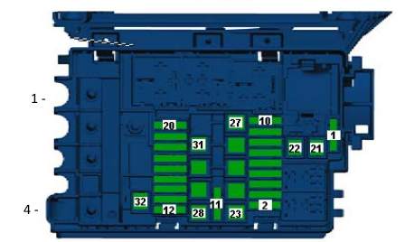
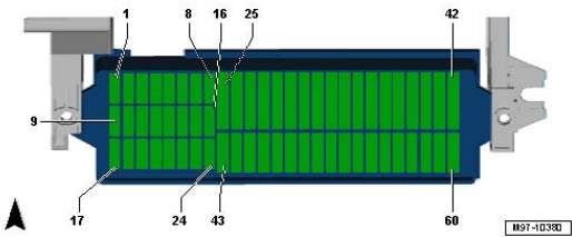
Passenger compartment
Located under the instrument panel on the driver’s side, behind the protective cover.
Fuse box diagram
| No. | Description |
| 1 | 5A – BU 2 blind spot check |
| 2 | 10A – Control unit for alarm connection module and communication unit |
| 3 | 5A – Device combination BU |
| 4 | 5A – Receive – telephone transmission device |
| 5 | 10A – instrument cluster control unit;
On-board power control unit; Left fog lamp. |
| 6 | 10A – Release button on rear door handle;
Reversing camera. |
| 7 | 5A – Dimmer for lighting switches and instrument clusters;
License plate illumination. |
| 8 | 10A-Windshield washer pump |
| 9 | 5A – Airbag control unit;
Front passenger front airbag deactivation warning light; Seat occupancy recognition control unit. |
| 10 | 15A – Intermittent Wiper Switch |
| 11 | 5A – Lighting Switch |
| 12 | Reservation |
| 13 | 5A – Start-stop button;
Folding mirror switch; Tire pressure indicator knob; Reversing light switch; High pressure sensor; Air pollution sensor; Heater controller; Park Assist Controller; Vehicle location system controller; Electrochromic interior mirror; Washer nozzle heating resistor. |
| 14 | 10A – Cruise control switch;
Tiptronic switch; Oil level and temperature sensor; Additional instruments; ABS controller; Cluster instrument controller; Power steering controller; Steering column control; Voltage stabilizer; Data bus diagnostic interface; Fuel pump controller; Shift lever sensor controller; Engine controller; Crankcase heating resistor. |
| 15 | 5A – Dimmer for lighting switches and instrument clusters;
Air flow meter; Control unit for the vibration damping system; Headlight range control actuator; Connector, 16-pin; Diagnostic connector. |
| 16 | 5A – Motor control unit |
| 17 | 10A – Interior monitoring system sensor;
Vehicle roll sensor; Alarm siren. |
| 18 | 15A – Low Beam Lamp Left |
| 19 | 15A – Right-hand dipped beam headlight |
| 20 | 10A – Tiptronic switch;
Heater control unit; Automatic transmission control unit; Climate control unit; Climate control unit; Shift lever sensor control unit; Solenoid of the ignition key removal lock. |
| 21 | 15A – Onboard Power Control Unit |
| 22 | 5A – Ignition and start switch;
Vehicle tracking control unit. |
| 23 | 10A – Rain and light sensor;
On-board power control unit; Telephone transceiver; Control unit for emergency call module and communication unit; Connector, 16-pin -T16-; Diagnostic connector; Additional devices. |
| 24 | 10A – On-board power control unit;
Control unit for access and takeoff privileges; Electric steering column lock; Data bus diagnostic interface. |
| 25 | 10/25A Automatic transmission controller;
Multifunction switch; DSG mechatronic unit. |
| 26 | 30A – Brake system vacuum pump |
| 27 | Reservation |
| 28 | 25A – Terminal 75 Power Relay 1 |
| 29 | 5A – On-board power control unit |
| 30 | 20A – Blocking diode;
Lighter; 12V socket. |
| 31 | 30A – Light Switch |
| 32 | 15A – Fog Light Switch |
| 33 | 40A – Heater control unit;
Air conditioning control unit. |
| 34 | 10/15A – Instrument cluster control panel;
On-board power distribution board; Left headlight for headlights; Right road headlight bulb; Headlights. |
| 35 | 10A – Steering column control unit |
| 36 | 30A – Onboard Power Control Unit |
| 37 | 5A – Left Daytime Running Light |
| 38 | 5A – Correct daytime running light bulb |
| 39 | 30A – Relay for manual low beam and signal lamp (high beam) |
| 40 | Reservation |
| 41 | Reservation |
| 42 | Reservation |
| 43 | 30A – Front passenger door control unit |
| 44 | 30A – On-board power control unit |
| 45 | 30A – Driver’s Door Controller |
| 46 | Reservation |
| 47 | 20A – Fuel Pump Relay |
| 48 | 30A – On-board power control unit |
| 49 | 40A – Supply fan control unit |
| 50 | 30A – Front Seat Heating Controller |
| 51 | 30A – Sliding Roof Control Unit |
| 52 | 20A – Onboard Power Control Unit |
| 53 | |
| 54 | 25A – Automatic Transmission Control Unit |
| 55 | 20A – Light switch, dipped beam and light switch (including high beam) |
| 56 | 20A – Onboard Power Control Unit |
| 57 | 25A – Control unit with navigation system with display, main unit |
| 58 | 10A – Reducing agent dosing system relay |
| 59 | Reservation |
| 60 | Reservation |