Volkswagen Golf Plus – Fuse box diagram
Year of manufacture: 2005, 2006, 2007, 2008, 2009, 2010, 2011, 2012, 2013, 2014.
Cigarette lighter fuse (power socket) in the Volkswagen Golf Plus Is a 30 (20A) fuse in the fuse box in the passenger compartment.
Passenger compartment
Fuse box
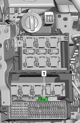
The main fuse box is located behind the hinged glove box on the driver’s side.
From the top is the main unit with relay. There may also be a thermal fuse for the driver’s seat adjustment: 1 – 20A.
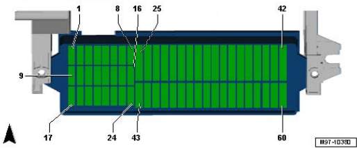
There are 2 different versions of the fuse box possible. They differ in the number of elements 58 and 60.
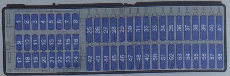
Type 1
Description
| 1 | 10A Startup and Entry Clearance Control Unit |
| 2 | 10A Startup and Entry Authorization Control Unit |
| 3 | |
| 4 | |
| 5 | |
| 6 | |
| 7 | |
| 8 | |
| 9 | 5A Airbag control unit and front passenger front airbag deactivation warning light |
| 10 | |
| 11 | |
| 12 | 10A Control unit for adaptive lighting and headlight range control on the left side |
| 13 | 5A / 15A Controller for parking assistance;
Climatronic Controller; Heating switch and mode selector; Fresh air blower relay; ASR and ESP off button and its indicator light; Tire pressure indicator button; Reversing light switch; Air pollution sensor; Electrochromatic interior mirror; Start-stop mode button. |
| 14 | 10A / 15A Backplane diagnostic interface;
Instrument cluster control unit; Gear shift lever; Light switch; ASR and ESP disable button; Tire pressure indicator button; Brake light switch; Multifunction switch; Tiptronic switch; Fuel pump relay; Power steering control unit; ABS control unit; Starter Relay; Trailer detection control unit; Engine control unit. |
| 15 | 10A Headlight range control;
Air mass meter; Heating resistor for crankcase ventilation; Fresh air blower relay; Shift lever sensor control unit; Adaptive lighting and headlight range control unit; Left headlight range control actuator. |
| 16 | 10A / 15A Adaptive lighting and range control system control unit of headlights on the right side |
| 17 | 5A Instrument cluster control unit |
| 18 | 10A Control unit for cell phone control electronics |
| 19 | |
| 20 | 10A Gearshift Lever;
Climate control unit. |
| 21 | 20A On-board power control unit;
Left rear door control unit (central locking) |
| 22 | 10A Interior sensor;
Alarm siren. |
| 23 | 10A Camera reversing control unit;
Light switch; Rain and light sensor; Diagnostic socket; Heated rear window relay; On-board power supply control unit. |
| 24 | 10A Driver’s door control unit (central locking);
Passenger door central control unit (central locking). |
| 25 | |
| 26 | 20A Brake vacuum pump |
| 27 | |
| 28 | |
| 29 | 20A Rear wiper motor |
| 30 | 20A Lighter |
| 31 | |
| 32 | |
| 33 | 40A Supply fan relay |
| 34 | |
| 35 | |
| 36 | |
| 37 | |
| 38 | |
| 39 | |
| 40 | 15A Trailer recognition control unit |
| 41 | 15A Trailer recognition control unit |
| 42 | 20A Trailer recognition control unit |
| 43 | 30A Inverter with plug, 12V – 230V |
| 44 | 25A Rear window heating, supply air ventilation relay |
| 45 | 30A Driver port control (power window);
Front passenger door (power window) controller. |
| 46 | 30A Left rear door control (power window);
Right rear door (power window) controller. |
| 47 | 15A Fuel pump and its relay |
| 48 | 20A On-board power control unit |
| 49 | 40A Supply fan control unit |
| 50 | 30A Front seat heating control unit |
| 51 | 20A sliding roof control unit |
| 52 | 20A relay for headlight cleaning system |
| 53 | 15A Electric motor for longitudinal adjustment of the lumbar support |
| 54 | 5A PDA control unit |
| 55 | |
| 56 | |
| 57 | 15A Main unit |
| 58 | |
| 59 | |
| 60 |
Type 2
Description
| Description | Number (next in parentheses amps) |
| Traction – coupling device | 2 (5), 39 (15), 40 (15), 41 (20). |
| ABS | 14 (5), 18 (5) |
| Tilt sensor | 43 (5) |
| Braking Signals | 13 (10) |
| Brake Light Switch | 14 (5) |
| Windshield lifters | 45 (30) |
| Rear window elevators | 46 (30) |
| Fan | 33 (40) or 56 (40) |
| Heated rear window | 44 (25) |
| Rear window washer | 28 (15) |
| Ultrasound in the salon | 43 (5) |
| Fuel Pump | 47 (15) |
| Headlight range control | 3 (5) |
| External socket | 53 (15) |
| Parktronic | 55 (5) |
| Remote Control | 4 (5) |
| Rain Sensor | 42 (5) |
| Headlight Washers | 52 (20) |
| Elektroluk | 51 (25) |
| Seat heating | 13 (5), 31 (5), 50 (30) |
| Fuel filler flap | 48 (25) |
| Phone | 10 (5) |
| Central locking system of the front door | 24 (10) |
| Rear door central locking system | 48 (25) |
| Lighter | 49 (25) |
| Rear socket | 54 (20) |
| 230V Socket | 37 (30) |
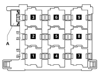
Relay box
Description
- J496 – Relay for auxiliary coolant pump (449)
- J39 – Headlight cleaning system relay (53)
- J17 Fuel pump relay (449) / J643 Fuel pressure relay (449)
- J1З – supply air fan relay (404)
- J333 – fuel pump cut-off relay (404)
- not used
- J485 – Relay for auxiliary heater operation (449)
- J682 – Power relay for terminal 50 (433), as of May 2006 (53)
- – not used
A – thermal fuse S44 1 for driver’s seat adjustment 30 A
J17 and J643 are mini relays and are installed (depending on the equipment) in a single relay block socket.
Engine compartment
Located next to the battery. Two fuse boxes and high-power fuses are located here.
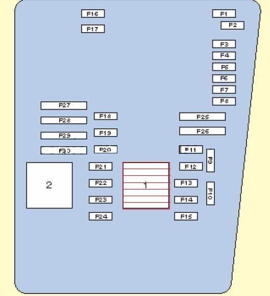
Description
| 1 | Motor control relay |
| 2 | Exhaust air pump relay |
| F1 | (30A) Windshield Wiper |
| F2 | (5A) Electronic steering column control module;
(30A) DSG gearbox mechatronic unit. |
| F3 | (5A) On-board power control unit |
| F4 | (30A) ABS control module |
| F5 | (15A) Transmission control module |
| F6 | (5A) Instrument panel |
| F7 | (40A) Power relay |
| F8 | (15A) Audio system/main unit |
| F9 | (5A) Telephone control unit |
| F10 | (5A/10A) Electronic motor control unit |
| F11 | (20A) Additional heater control unit |
| F12 | (5A) CAN data bus, gate control unit; |
| F13 | (15A / 30A) Electronic motor control unit |
| F14 | (20A) Engine Management System, Ignition Coil |
| F15 | (5A/10A) Engine Management System, lambda sensor |
| F 16 | (30A) ABS control module, right side reflector |
| F17 | (15A) Horn |
| F18 | (30A) Audio system |
| F19 | (30A) Windscreen wiper and washer system |
| F20 | (10A) Coolant pump |
| F21 | (10A / 15A) Motor management system;
Lambda Probe; Magnetic clutch for drive fan. |
| F22 | (5A) Clutch pedal position switch |
| F23 | (5A/10A/15A) Engine management system;
Fuel pressure regulator; Secondary air pump relay. |
| F24 | (10A) Engine management system;
EGR valve; Solenoid valve. |
| F25 | (40A) ABS control unit |
| F26 | (30A) Left Reflector |
| F27 | (50A) Control module for glow plugs |
| F28 | (40A) Main Ignition Circuits |
| F29 | (50A) Thermal fuse 1 for seat adjustment |
| F30 | (40A) Starting system;
(50A) Discharge contact relay X. |
Fuse connection diagram
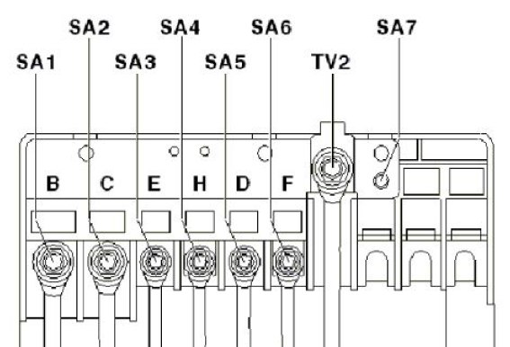
- 150 / 200А – Generator
- 80А – Power steering
- 50A – Radiator Fan
- 80A – High Heater Relay
- 80A – Terminal 30 connector, fuse box
- 40A – Low Power Heating Relay
- 50A – Terminal 30 connector, fuse box