Volvo XC70 (2003) – fuse box diagram
Year of manufacture: 2003.
Cigarette lighter fuse (electrical outlet) in the Volvo XC70 (2003). Is fuse 13 in the fuse box on the edge of the instrument panel.
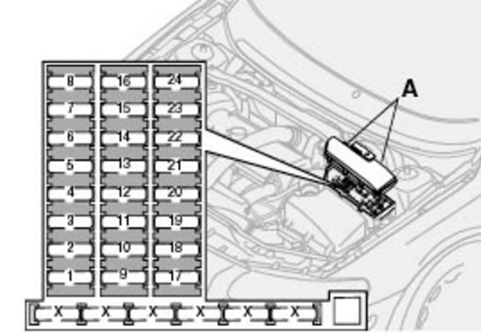
Fuses – engine compartment
| Number | Description | Amps [A] |
| 1 | Accessories | 25 |
| 2) | Additional lights (optional) | 20 |
| 3) | Vacuum Pump | 15 |
| 4 | Oxygen sensors | 20 |
| 5 | Crankcase heater;
Solenoid valves. |
10 |
| 6 | Mass airflow sensor;
Engine control module; Injectors. |
15 |
| 7 | Accelerator module | 10 |
| 8 | Air conditioning compressor;
Accelerator pedal position sensor; Electric box fan. |
10 |
| 9 | Horn | 15 |
| 10 | Rear Door Windshield Wiper | 10 |
| 11 | Air conditioning compressor;
Ignition coils. |
20 |
| 12 | Brake Light Switch | 5 |
| 13 | Cleaners | 25 |
| 14 | ABS / STC / DSTC | 30 |
| 15 | – | – |
| 16 | Windshield washers;
Windshield wiper and washer (some models) |
15 |
| 17 | Light crossing, right | 10 |
| 18 | Passing lights, left | 10 |
| 19 | ABS / STC / DSTC | 30 |
| 20 | Traffic Light Left | 15 |
| 21 | Traffic lights on the right | 15 |
| 22 | Starter | 25 |
| 23 | Motor control module | 5 |
| 24 | – | – |
Fuse box on the edge of the instrument panel
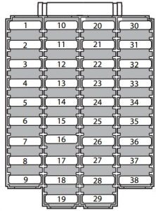
| Number | Description | Amps [A] |
| 1 | Dipped beams | 15 |
| 2) | Traffic Lights | 20 |
| 3) | Electric driver’s seat | 30 |
| 4 | Electric passenger seat | 30 |
| 5 | – | – |
| 6 | – | – |
| 7 | Heated seat – left front (optional) | 15 |
| 8 | Heated seat – right front (optional) | 15 |
| 9 | ABS / STC / DSTC | 5 |
| 10 | – | – |
| 11 | – | – |
| 12 | Headlight cleaners (some models) | 15 |
| 13 | 12 V electrical socket (cigarette lighter) | 15 |
| 14 | Electric passenger seat | 5 |
| 15 | Audio System, VNS | 5 |
| 16 | Public Address System | 20 |
| 17 | Sound Amplifier | 30 |
| 18 | Front fog lamps | 15 |
| 19 | VNS View | 10 |
| 20 | – | – |
| 21 | Automatic transmission;
Shiftlock; Extended D2 feed. |
10 |
| 22 | Direction indicators | 20 |
| 23 | Headlight switch module;
Air conditioning system; On-board diagnostic connector; Steering lever modules. |
5 |
| 24 | D1 extended power relay;
Air conditioning system; Electrically adjustable driver’s seat; Driver information. |
10 |
| 25 | Ignition switch;
Starter Relay; SRS; Motor control module. |
10 |
| 26 | A/C system fan | 30 |
| 27 | – | – |
| 28 | Electronic module – auxiliary lighting | 10 |
| 29 | – | – |
| 30 | Parking lights left front and rear | 7,5 |
| 31 | Front and rear parking lights on the right;
License plate lights. |
7,5 |
| 32 | Central electrical module;
Mirror illumination in the sun visor; Glove box illumination; Interior lighting. |
10 |
| 33 | Fuel Pump | 15 |
| 34 | Opening Roof Actuator | 15 |
| 35 | Central locking, power windows – left mirror | 25 |
| 36 | Central locking, power windows – right mirror | 25 |
| 37 | Electrically Operated Rear Windows | 30 |
| 38 | Alarm siren | 5 |
Fuses in the cargo compartment
The fuses in the cargo compartment are located behind the panel on the driver’s side of the cargo compartment
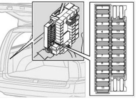
| Numerr | Description | Amps [A] |
| 1 | Rear electrical module;
Load compartment lighting. |
10 |
| 2) | Rear fog light | 10 |
| 3) | Stoplights | 15 |
| 4 | Support Lights | 10 |
| 5 | Rear window defroster;
15I courier – accessories. |
5 |
| 6 | Unlock the backdoor | 10 |
| 7 | Additional 12 V socket in the load compartment
(optional) |
15 |
| 8 | Central tailgate lock;
Fuel filler flap. |
20 |
| 9 | Trailer (30 channels) | 15 |
| 10 | CD changer, VNS | 10 |
| 11 | Accessory Equipment Control Module (AEM) | 15 |
| 12 | Rear Door Windshield Wiper | 15 |
| 13 | Speaker loading space
(subwoofer) – optional |
15 |
| 14 | Stoplights | 7,5 |
| 15 | Trailer hitch (15I) | 20 |
| 16 | – | – |
| 17 | Four-wheel drive control module | 7,5 |
| 18 | – | – |