Fuse and relay box diagrams – Renault Master
Applies to vehicles manufactured over the years:
2003, 2004, 2005, 2006, 2007, 2008, 2009 i 2010.
As the Renault master was produced over a long period of time with different electrical equipment options and body models, it is not possible to give a general description of fuses and relays.
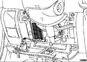
Passenger compartment
Fuse box
Located under the dashboard behind the protective cover.
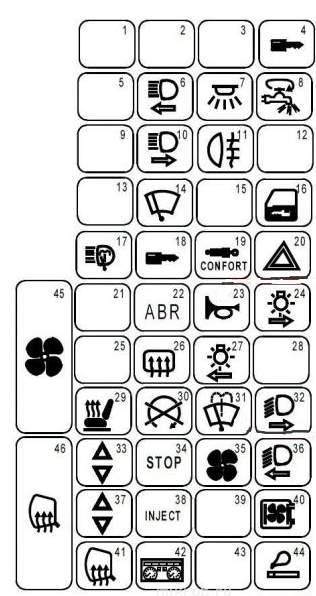
Description
- Reservation
- Reservation
- Reservation
- 20A – Anti-theft device, shock sensor
- Reservation
- 10A – Left High Beam Headlamp, Instrument Panel
- 15A – Plafond, Audio system memory, Instrument panel, Receiver for remote door lock control, Interior lighting, Index with built-in clock, Door lock control relay, Tachograph
- 30A – Deflection of fuses of electricity consumers.
- Backup
- 10A – Right headlight (high beam).
- 7.5A – Rear fog lamps, instrument panel
- Reservation
- Reservation
- 20A – Wiper Motor
- Reservation
- 25A – Central door locking system
- 30A – Headlight Washer
- 2A – OBD2 on-board diagnostic connector
- 5A – Air Suspension
- 15A – Alarm, Diagnostic Connector
- Reservation
- 2A – Anti-lock braking system (ABS).
- 15A – Audible Signal
- 7.5A – right side lamps, license plate illuminated
- Reservation
- 5A – Rear Window Heating Element
- 20A – Left side lamps, license plate lamps, control lamps and cigarette lighter switch illumination lamps
- Reservation
- 15A – Heated seat
- 20A – Diesel engine stop solenoid valve, heated system, injection system.
- 15A – Wiper, windshield washer.
- 10A – Right Headlight (Low Beam)
- 25A – Electric Passenger Glass Door Lifter
- 20A – Stop Lamps, Reversing Lamps
- 20A – Electric Fan for cab air supply
- 10A – Headlight washer timer relay, left headlight (low beam), instrument panel
- 25A – Electrically Operated Window in Driver’s Door
- 7.5A – Injection System ECU
- Reservation
- 20A – Audio System, Tachometer Relay, Diesel Heater Relay
- 10A – Elements for heating the outside rear view mirrors.
- 15A – Exterior light off signal, Instrument panel
- Reservation
- 25A – Lighter
- 40A – Electric air supply fan for the cabin of an air-conditioned car
- 40A – Rear Window Heating Element
Relay box
These modules are mounted on the cabin relay board on the left strip of the dashboard.
Type 1
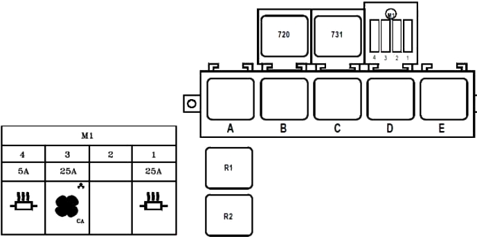
Description
| F1 | 25 | Bus for 9 passengers:
+Battery heating before the battery heating output is cut off. |
| F2 | – | Bus for 9 passengers:
not used |
| F3 | 25 | Bus for 9 passengers:
Capacitor Relay |
| F4 | 5 | Bus for 9 passengers:
+ battery supply before the battery is cut off heating control |
| A | + After Ignition 1 | |
| B | Not in use | |
| C | Passenger compartment fan mounting speed 4 | |
| D | Independent heating cut-off | |
| E | Heated rear screen and side mirrors | |
| R1 | Bus for 9 passengers:
Air conditioning + power after ignition |
|
| R2 | Bus for 9 passengers:
Condenser |
|
| 720 | Air conditioning cut-off | |
| 731 | Heated windscreen | |
Type 2
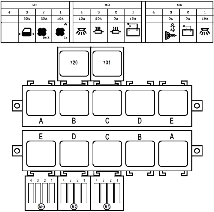
Description
| F1 | 15 | Capacitor Relay |
| F2 | 25 | + After Ignition Relay 2 |
| F3 | 30 | Power supply to the door when the battery is cut off |
| F4 | – | Not in use |
| F1 | 15 | Battery cut-off relay |
| F2 | 5 | + battery power supply before battery shutdown heating control |
| F3 | 25 | + Battery power supply before battery cutout heating output |
| F4 | 15 | Light and foot signals + battery power when battery is cut off |
| F1 | 10 | + ignition relay power supply 2 (299-752) – power door – passenger light – central locking. |
| F2 | 5 | Emergency stop – switch open |
| F3 | 5 | Rear door locks + after ignition |
| F4 | – | Not in use |
| 720 | Air conditioning cut-off | |
| A | + After Ignition 1 | |
| B | Fog lamps | |
| C | Passenger compartment fan mounting speed 4 | |
| D | Independent heating cut-off | |
| E | Heated rear screen and side mirrors | |
| A | Battery cutoff | |
| B | Battery disconnect lock | |
| C | + After Ignition 2 | |
| D | Evaporator | |
| E | Condenser | |
Battery Tracks
These fuses are located on the positive terminal of the battery.
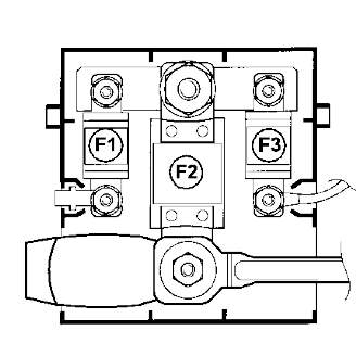
- F1 40A passenger compartment fuse box
- F2 – 400A – Fuse box power supply for power circuits, starter, starter system
- F3 – 40A – Fuse for injection computer power relay