
KIA Sportage 3 (SL) (2010-2015) – Fuse box diagram
Year of manufacture: 2010, 2011, 2012, 2013, 2014, 2015.
Lighter fuse (electrical outlet) in KIA Sportage 3 (SL) (2010-2015). Is fuse F33 in the fuse box in the passenger compartment.
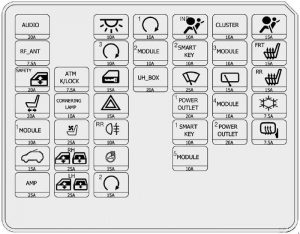
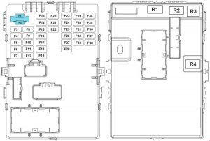
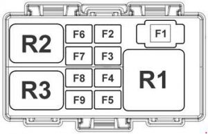
Passenger compartment fuse box
| No. |
Amp [A] | Fuse |
Description |
| F1 | 20 | AUDIO | Audio.
A/V main unit and navigation, F13 10A (interior light) |
| F2 | 7.5 | RF ANT | RF Receiver |
| F3 | 20 | PAVDW SECURITY | Driver’s electrical safety window module |
| F4 | 20 | P / SEAT (DRV) | Driver’s seat manual switch |
| F5 | 10 | MODULE 1 | Driver CCS switch;
Data link connector; Rear parking assistance buzzer; External mirror power switch. |
| F6 | 15 | SUNROOF | Roof Engine |
| F7 | 25 | AMP | AMP |
| F8 | 7.5 | ATM K / LOCK | ATM gear shift lever;
Key electromagnet. |
| F9 | 10 | CORNER LAMPS | – |
| F10 | 15 | HEADQUARTERS CENTER | Driver/passenger CCS airbag heater |
| Fll | 25 | PAVDW RH | Main window switch;
Right rear window switch; Passenger window switch (LHD). |
| F12 | 25 | PAVDW LH | Main window switch;
Left rear window switch; Passenger window switch (RHD). |
| F13 | 10 | FOURTH LP | Air conditioning control module, with
Digital clock, with IPS control module indicator set (IND.), Startup lighting; Ignition key ILL..; Door warning switch; Driver and passenger interior light; Top console (map light switch); BCM. |
| F14 | 10 | PDMB | Intelligent key control module;
FOB handle; Start / Stop button. |
| F15 | 15 | DR LOCK | Close and unlock door relay;
Tailgate relay. |
| F 16 | 15 | HAZARD | BCM |
| F17 | 10 | FOG LP RR | ICM relay box
(rear fog light relay) |
| F18 | 15 | STRHTD | – |
| F19 | 25 | PDM | Intelligent Key Control Module |
| F20 | 10 | START | Intrusion alarm relay;
Intelligent key control module; E/R fuse and relay box (R4); Transmission range switch. |
| F21 | 10 | MODULE 2 | Stop light switch (GSL);
ATM gear lever indicator; IPS control module (ON / START input); 4WD ECM; Headlight leveling device switch; Headlight leveling device actuator – left and right; Control module for the automatic headlight leveling device. |
| F22 | 20 | UH BOX | I/O fuse and relay box
(FUSE – F22, F23, F24, F25) |
| F23 | 10 | A / BAG IND | Instrument grouping (IND.) |
| F24 | 10 | SMART KEY 2 | Intelligent Key Control Module |
| F25 | 25 | WIPER FRT | Front wiper motor;
Multifunction switch (windshield wiper); I/O fuse and relay box (R12 – front wiper relay (LO)). |
| F26 | 20 | POWER OUTLET 1 | Front power socket – right |
| F27 | 10 | SMART KEY 1 | Smart Key Control Module;
BCM. |
| F28 | 10 | MODULE 5 | Digital Clock;
Audio; Amplifier; A/V main unit and navigation; External mirror power switch. |
| F29 | 10 | CLUSTER | Instrument grouping (IND.);
Alternator; Indicator light; BCM; Digital Clock; Air conditioning control module; Driver and passenger seat heating switch; Driver’s CCS control module; A/V main unit and navigation, |
| F30 | 10 | IG2 | Intelligent control module;
BCM; IPS control module. |
| F31 | 15 | WIPER RR | ICM relay box (rear wiper relay);
Rear wiper motor; Multi-function switch (windshield wiper). |
| F32 | 10 | MODULE 4 | Air conditioning control module;
Cluster ioniser; Sunroof Engine; Electrochromic mirror; Diesel box (RLY.2,3 – PTC heater relay no.2, no.3); E/R fuse and relay box (R1 – blower relay). |
| F33 | 20 | POWER OUTLET 2 | Front power socket and cigarette lighter (left);
Rear power socket. |
| F34 | 15 | AIR BAG | SRS control module |
| F35 | 15 | S / FRT HEATER | Driver and passenger seat heater switch |
| F36 | 15 | S / HEATER RR | Rear seat heater switch |
| F37 | 7.5 | A / CON | Air conditioning control module (Auto) |
| F38 | 7.5 | HTD MIRR | Driver and passenger exterior power mirror;
Air conditioning control module. |
| Relay | |||
| R1 | Backdoor relay | ||
| R2 | Intrusion Alarm Relay | ||
| R3 | Door Lock/Unlock | ||
| R4 | Window Lifter Relay | ||
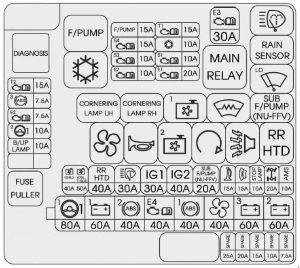
Engine compartment fuse box
| No. |
Amp [A] | Fuse |
Description |
| F1 | 80 | MDPS | MDPS Unit |
| F2 | 60 | B + 1 | Junction box l / P (fuse-F15 / F16 / F17 / F19)
Control Module IPS-IPS 4 / IPS 5 / IPS 6 / IPS 7) |
| F3 | 40 | ABS 2 | ESP control module;
ABS control module; Universal control connector. |
| F4 | 40 | EMS | EMS Box (fuse – F1 / F2 / F3 / F6) |
| F5 | 40 | ABS 1 | ESP control module;
ABS control module. |
| F6 | 40 | BLOWER | R1 (blower relay) |
| F7 | 60 | B + 3 | Junction box l / P
(fuse – F3 / F4 / F8 / F9 / F10 / F13 / F14, Power connector – F1 / F2) |
| F8 | 60 | B + 2 | Junction box l / P
(Power window relay, fuse – F5 / F6 / F7, IPS control module – IPS 0 / IPS 1 / IPS 2 / IPS 3 / IPS 8) |
| F9 | 40 | COOUNG FAN | R3 (cooling fan relay (low)),
RLY 9 (cooling fan relay (high)) |
| F10 | 40 | COOUNG FAN | RLY 6 (rear defogger relay) |
| F12 | 30 | IG1 | No smart key:
Ignition switch; With intelligent key: PDM relay box (IGN1 relay). |
| F13 | 40 | IG2 | RLY 4 (start relay);
Without smart switch: w Ignition switch; With intelligent key: PDM relay box (IGN2 relay). |
| F14 | 20 | SUB F / PUMP | F4NA: RLY 11 (auxiliary fuel pump relay) |
| F15 | 15 | HORN | RLY 2 (horn relay),
RLY 5 (anti-theft alarm relay) |
| F 16 | 15 | DEICER | Not used |
| F17 | 10 | STOP LAMPS | Stop light switch;
Smart key control module; Electronic stop signal module. |
| F18 | 20 | 4WD | ECM 4WD |
| F19 | 10 | AMS | Not used |
| F21 | 10 | B/UP LAMP | Reversing light switch;
Rear combination lamp (removed); Electrochromic mirror; Audio unit; AN and navigation unit. |
| F22 | 10 | MDPS2 | MDPS Unit |
| F23 | 7.5 | 2 ECUS | PCM / ECM, G4KE:
Clock spring (remote control); Mass airflow sensor. |
| F24 | 7.5 | ABS | ESP control module;
ABS control module; Multifunction switch; Steering angle sensor; Universal control connector; Diesel Box (R4 – fuel filter heater relay); Glow relay module; Fuel filter warning sensor. |
| F25 | 15 | TCU2 | Thruster bridge range switch |
| Relay | |||
| R1 | Blower relay | ||
| R2 | Horn relay | ||
| R3 | Cooling fan relay (low) | ||
| R4 | Start relay | ||
| R5 | Intruder alarm horn relay | ||
| R6 | Rear defogger relay | ||
| R7 | – | ||
| R8 | – | ||
| R9 | Cooling fan relay (high) | ||
| R10 | Front Windshield Wiper Defrost Relay | ||
| R11 | ATM P / N Relay | ||
| R12 | Windshield wiper relay (low) | ||
| R13 | Windshield wiper relay (rain sensor) | ||
| R14 | |||
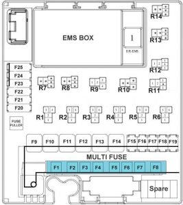
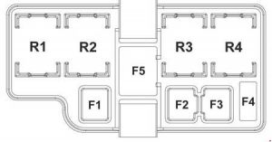
EMS box (engine compartment fuse box)
| No. |
Amp [A] |
Fuse |
Description |
| F1 | 30 | ECU | R1 (motor control relay) |
| F2 | 15 | TCU 1 | D4HA, G4FD:
MTC; G4KD, D4FD, G4KE: PCM; G4NA, F4NA: PCM (A / T); ECM (M / T). |
| F3 | 10 | A / CON | R3 (air conditioning relay) |
| F4 | 10 | SENSOR 1 | G4KD, G4KE, F4NA:
Immobilizer; Crankshaft position sensor module; Camshaft sensor # 1/2; Oil control valve 1/2; Canister purge valve controls; Variable intake manifold; D4HA: EGR Cooling Bypass Solenoid Valve; Diesel Box ( RLY.1 – PTC heater relay no.1); VGT electric actuator; E/R fuse and relay box; (RLY. 3 – cooling fan relay (low); RLY.9 – cooling fan relay (high)); Oil level sensor; G4NA: Immobilizer module; Camshaft position sensor 1/2; Injector no. 1/2/3/4; D4FD, G4FD: Immobilizer module; Oil control valve no. 1/2; Container purge control solenoid valve; Variable intake manifold valve. |
| F5 | 20 | 1 ECU | G4KD, G4KE, F4NA, G4NA, D4FD, G4FD:
coil ignition coil #1/2/3/4; Condenser; D4HA: ECM. |
| F6 | 15 | FUEL PUMP | R2 (fuel pump relay) |
| F7 | 15 | SENSOR 4 | G4KD, G4KE, G4NA:
R2 (fuel pump relay); Upper / lower oxygen sensor; I/O fuse and relay box (R3 – cooling fan relay (low); R9 – cooling fan relay (high)); D4HA: Immobilizer module; Rail pressure regulating valve; Fuel pressure regulating valve; RLY. 2 (fuel pump relay); F4NA: RLY. 2 (fuel pump relay); Oxygen sensor up/down; ECM (M / T); I/O fuse and relay box (RLY. 3 – cooling fan relay (low); RLY.9 – cooling fan relay (high),; RLY.11 – auxiliary fuel pump relay); Cold start solenoid valve; D4FD, G4FD: RLY. 2 (fuel pump relay); PCM, top/bottom oxygen sensor; I/O fuse and relay box (RLY. 3 – cooling fan relay (low); RLY. 9 – cooling fan relay (high)). |
| F8 | 10 | SENSOR 3 | G4KD, G4KE, F4NA::
R3 (air conditioning relay); Injector no. 1/2/3/4; D4HA: RLY. 3 (air conditioning relay); Crankshaft position sensor; probe lambda; G4NA: RLY. 3 (air conditioning relay); Oil control valve no. 1/2; Container emptying control solenoid valve; Variable speed intake manifold valve. |
| F9 | 10 | SENSOR 2 | G4FD, G4KD , D4FD, G4KE, G4NA, F4NA : –
D4HA: Light Switch stop. |
| Relay | |||
| R1 | Motor control relay | ||
| R2 | Fuel pump relay | ||
| R3 | Air conditioning relay | ||
Main fuse
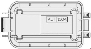
Engine compartment fuse panel (diesel engine only)

| No. |
Amp [A] | Description |
| F1 | 50 | PTC heater relay #1 |
| F2 | 50 | PTC heater relay #2 |
| F3 | 50 | PTC heater relay #3 |
| F4 | 30 | Fuel filter heater relay |
| F5 | 80 | Glow relay module |
| Relay | ||
| R1 | PTC heater relay #1 | |
| R2 | PTC heater relay #2 | |
| R3 | PTC heater relay #3 | |
| R4 | Fuel filter heater relay | |