Mercedes Sprinter (W901, W902, W903, W904, W905) – Fuse box diagram
Year of manufacture: 1995, 1996, 1997, 1998, 1999, 2000, 2001, 2002, 2003, 2004, 2005, 2006.
Lighter fuse (front) – Fuse box in engine compartment. – Fuse F8/20A
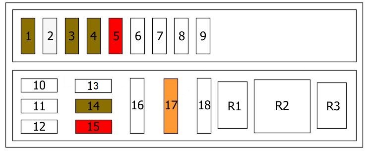
Passenger compartment fuse box
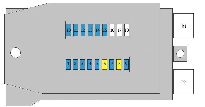
Fuse box diagram (1995-2000)
| No. | Amps [A] | Description |
|---|---|---|
| 1 | 15A | Right parking light;
Right rear light. |
| 2 | 15A | Right main beam |
| 3 | 15A | Traffic light on the left;
Traffic light. |
| 4 | 15A | Reversing lights;
Warning lights. |
| 5 | 15A | Brake lights;
Heated wash nozzles. |
| 6 | 20A | Windshield Wipers |
| 7 | 15A | Horn;
Heated rear window; Immobilizer. |
| 8 | 20A | Interior lighting;
Diagnostic connector; Lighter. |
| 9 | 15A | Emergency Lights |
| 10 | 15A | Instrument Illumination |
| 11 | 15A | Left parking light;
Left taillight. |
| 12 | 15A | Right dipping beam |
| 13 | 15A | Passing the light on the left;
Rear fog light(s). |
| 14 | 15A | Front fog light(s);
Rear fog light(s). |
| 15 | 15A | Radio airbag |
| 16 | Backup fuse/relay | |
| 17 | Backup fuse/relay | |
| 18 | Backup fuse/relay | |
| R1 | Windshield Wiper Relay | |
| R2 | Indicator relay |
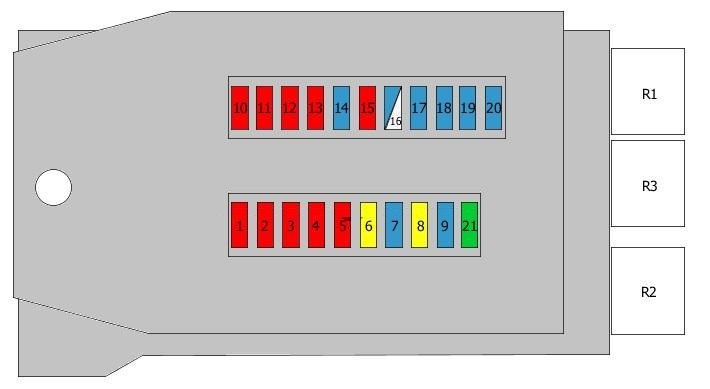
Fuse box diagram (2000-2006).
| No. | Amps [A] | Description |
|---|---|---|
| 1 | 10 A | Right rear light;
Right side light. |
| 2 | 10 A | Right main beam |
| 3 | 10 A | Traffic light on the left;
Traffic light. |
| 4 | 10 A | Reversing lights |
| 5 | 10 A | Stop lights |
| 6 | 20A | Windshield Wiper Motor |
| 7 | 15A | Horn;
Heated rear window. |
| 8 | 20A | Interior lighting;
Radio; Lighter. |
| 9 | 15A | Emergency lights;
Parking lights. |
| 10 | 10 A | Instrument lighting;
License plate illumination. |
| 11 | 10 A | Left rear light;
Left side light. |
| 12 | 10 A | Dip beam on the right |
| 13 | 10 A | Passing the light on the left;
Rear fog light(s). |
| 14 | 15A | Fog lamps |
| 15 | 10 A | Radio |
| 16 | 15A | Engine Management |
| 17 | 15A | Engine Management |
| 18 | 15A | Ignition |
| 19 | 15A | Fuel pump relay;
Additional fuel pump relay. |
| 20 | 15A | Heating and Air Conditioning |
| 21 | 30A | Front Fan |
| R1 | Windshield wiper relay | |
| R2 | Indicator relay | |
| R3 | Engine Management Relay |
Under-seat fuse box
Fuse box diagram (type 1)
The assignment and description of the fuses and relays are printed on the fuse box cover.
| No. | Amps [A] | Description |
|---|---|---|
| 1 | 7,5A | Combination meter |
| 2 | 25A | Additional Heater |
| 3 | 7,5A | Buzzer |
| 4 | 7,5A | Buzzer |
| 5 | 10 A | Additional heater |
| 6 | ||
| 7 | ||
| 8 | ||
| 9 | ||
| 10 | ||
| 11 | ||
| 12 | ||
| 13 | ||
| 14 | ||
| 15 | ||
| 16 | ||
| 17 | ||
| 18 | ||
| R1 | Horn relay | |
| R2 | Special equipment | |
| R3 | Coolant pump relay |